
Specifications


2–14
FM500 User's Manual
Pin Number Function
1 Ground
2 (no connection)
3 Composite Out (sample of stereo generator output)
4 FSK In (Normally high; pull low to shift carrier
frequency approximately 7.5 kHz. Connect to open
collector or relay contacts of user-supplied FSK keyer.)
5 /Auto Carrier Off (Pull low to enable automatic turnoff
of carrier with program failure.)
6 Meter Battery (unregulated DC volts; 5 volts = 50 VDC)
7 Meter RF Watts (1 volt = 100 watts)
8 Meter PA Volts (5 volts = 50 VDC)
9 /Ext. Enable (Pull low to disable internal stereo
generator and enable External Composite Input.)
10 a) 38 kHz Out (From stereo generator for power supply
synchronization.)
b) For transmitters equipped with tuner option, this pin
becomes the right audio output for an 8–ohm monitor
speaker. 38kHZ Out is disabled.
11 ALC
12 /Carrier Off (pull low to turn carrier off.)
13 Fault Summary (line goes high if any fault light is
activated.)
14 Meter PA Temperature (5 volts = 100 degrees C.)
15 Meter PA Current (1 volt = 10 amperes DC.)
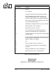
Illustration 2–15 Remote I/O Connector (outside view)
Table 2–3 Remote I/O Connections
1
15
8
9