
Specifications

3–7
Operation
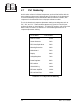
3.7 RF Output Control
Set this control for the desired output power level. Preferably, set the power with an
external RF wattmeter connected in the coaxial line to the antenna. You may also use
the RF power reading on the digital multimeter.
The control sets the RF output voltage. Actual RF output power varies as the approxi-
mate square of the relative setting of the control. For example, a setting of “50” is
approximately 1/4 full power. Operation below 100 watts is not recommended as
instability can occur which could damage the transmitter.
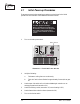
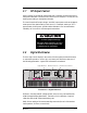
Illustration 3–3 Digital Multimeter
RF Power—Actually reads RF voltage squared, so the accuracy can be affected by
VSWR (Voltage Standing-Wave Ratio). See section 5.4 for calibration. Requires
calibration with the RF reflectometer being used.
SWR—Direct reading of the antenna standing-wave ratio (the ratio of the desired
load impedance, 50 ohms, to actual load).
FM500
FM BROADCAST TRANSMITTER
®
Power
Carrier
Modulation
Fault
Stereo
Mono RF Output
ProcessingInput Gain
Wide Band
High Band
Audio Input
High
Low
2
-6
-12
-18
2
+6 dB
+12 dB
10
20
Expand
Compress
RF Power
SWR
ALC
PA DC Volts
PA DC Amps
PA Temperature
Supply DC Volts
Voltmeter
SWR
Lock
Input
PA DC
PA Temp
Over
100
90
80
70
60
50
40
30
20
Pilot
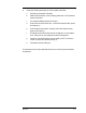
Digital Multimeter Multimeter Functions
Multimeter Push-buttons
CAUTION
Possible equipment damage!
Operation below 100 watts can cause
oscillations and other problems that
could damage the transmitter.
3.8 Digital Multimeter
The four-digit numeric display in the center of the front panel provides information
on transmitter operation. Use the “Up” and “down” push-buttons to select one of
the following parameters. A green LED indicates the one selected.