
Specifications


4–4
FM500 User's Manual
i
n
q
u
e
s
t
o
m
o
n
d
o
,
f
o
r
s
e
,
u
n
o
s
i
d
i
c
e
s
e
d
i
c
i
a
m
o
c
h
e
m
a
s
c
r
i
v
e
n
d
o
c
o
n
i
n
q
u
e
s
t
o
m
o
n
d
o
,
f
o
r
s
e
,
u
n
o
s
i
d
i
c
e
s
e
d
i
c
i
a
m
o
c
h
e
m
a
s
c
r
i
v
e
n
d
o
c
o
n
m
a
s
c
r
i
v
e
n
d
o
c
o
n
i
n
q
u
e
s
t
o
m
o
n
d
o
,
f
o
r
s
e
,
u
n
o
s
i
d
i
c
e
s
e
d
i
c
i
a
m
o
c
h
e
m
a
s
c
r
i
v
e
n
d
o
c
o
n
m
a
s
c
r
i
v
e
n
d
o
c
o
n
in
q
u
e
s
t
o
m
o
n
d
o
,
f
o
r
s
e
,
u
n
o
s
i
d
i
c
e
s
e
d
i
ci
a
m
o
c
h
e
m
a
s
c
r
i
v
e
n
d
o
c
o
n
s
e
d
i
c
i
a
m
o
c
h
e
m
a
s
c
r
i
v
e
n
d
o
c
o
n
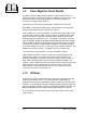
When either the positive or negative peaks of the output of U5 (U6) exceeds the
gain-reduction threshold, U13A generates DC bias, producing broadband gain
reduction. Q5 is a precision-matched transistor pair. Q5 and U13B form a log
converter, so that a given voltage change produces a given change in gain control
dB of U5 (U6). The log conversion ensures uniform level-processing characteristics
well beyond the 20 dB control range. The log conversion has an additional benefit;
it allows a display of gain control on a linear scale with even distribution of dB.
Q1 (Q2) is a recover/expansion gate with a threshold about 18 dB below the normal
program level. The amount of short-term expansion and gain reduction is
controlled by R650, located on the front panel display board. (See section 3.5.)
Pre-emphasis, in microseconds, is the product of the capacitance of C10 (C22),
multiplied by the gain of U8 (U9), times the value of R31 (R67). For a 75 µsecond
pre-emphasis, the gain of U8 (U9) will be about 1.11. Select the pre-emphasis curve
(75 µsec, 50 µsec, 25 µsec, or Flat) by jumpering the appropriate pins on header
JP1. Use trim pot R29 (R65) to make fine adjustments to the pre-emphasis. (See
section 5.1.)
For highband processing, the peak output of U10B is detected and gain-reduction
bias is generated, as with the broadband processor. The highband processing,
however, shifts the pre-emphasis curve rather than affecting overall gain.
Peak audio voltages are compared to a plus and minus 5 volt reference, U17 and
U18. This same reference voltage is used by the stereo generator, metering, and
display boards.
For an explanation of on-board adjustments see section 5.1.
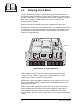
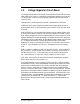
4.3 Stereo Generator Circuit Board
The stereo generator board (see Illustration 4–3) generates a composite stereo signal
from left and right-channel audio inputs. The component side of the board is
mostly a ground plane. Once again, the eighth-order, 15.2 kHz, elliptical, low-pass
filters (U201 and U202) are on this board, but belong to the audio processor.
Illustration 6–6 and accompanying schematic complement this discussion.
U207A and Y201 comprise a 7.6 MHz crystal oscillator from which the 19 kHz and
38 kHz subcarriers are digitally synthesized. U207F is a buffer. The 7.6 MHz is
divided by 5 in U208A to provide 1.52 MHz at pin 6, used by filters U201 and U202.
3.8 MHz, 1.9 MHz, and 304 kHz are also derived from dividers in U208.
Exclusive-OR gates, U210A and U210B, provide a stepped approximation of a 38 kHz
sine wave—a scheme described in the
CMOS Cookbook by Don Lancaster (Howard
W. Sams &. Co., Inc., Indianapolis, IN, 1978).
With the resistor ratios used, the synthesized sine wave has very little harmonic
energy below the 7th harmonic. U210C and D generate the 19 kHz pilot subcarrier.
U211 is a dual, switched-capacitor filter, configured as second-order, low-pass filters,