
Specifications


4–5
Principles of Operation
Illustration 4–3 Stereo Generator Board
each with a Q of 5. The 38 kHz and 19 kHz outputs of pins 1 and 20, respectively,
are fairly pure sine waves. Harmonic distortion products are better than 66 dB
down—THD of less than 0.05%.
U212 is a precision, four-quadrant, analog multiplier. The output of U212 is the
product of 38 kHz applied to the “X” input and the difference of left and right
audio (L-R signal) applied to the “Y” input. The resulting output is a double
sideband, suppressed carrier—the L-R subcarrier.
The SCA subcarrier, the left, right, and left-minus-right subcarriers, and the 19
kHz pilot subcarrier are combined into the composite stereo signal by summing
amplifier U206B.
Analog switch U205, at the input of U206B, provides switching of left and right
audio for stereo and mono modes. In the mono mode, right channel audio is
disabled, and the left channel audio is increased from 45% modulation to 100%.
MON L and MON R outputs go to the AF Monitor jacks on the rear panel.
R208+R210 (R220+R222) and C207 (C211) comprise a 75 µsec de-emphasis
network. Processed, de-emphasized (75 µsec) samples of the stereo generator
input signals are used for a studio monitor and for audio testing. Option jumpers
JP203 (JP204) allow you to select 50 µsec.
VR201 and VR202 supply +6 volts and –6 volts, respectively. A 5 volt reference
from the audio processor board supplies the subcarrier generators.
For an explanation of on-board adjustments see section 5.2.
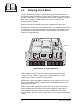
Stereo Generator
FM500
FM BROADCAST TRANSMITTER
®
Power
Carrier
Modulation
Fault
Stereo
Mono RF Output
ProcessingInput Gain
Wide Band
High Band
Audio Input
High
Low
2
-6
-12
-18
2
+6 dB
+12 dB
10
20
Expand
Compress
RF Power
SWR
ALC
PA DC Volts
PA DC Amps
PA Temperature
Supply DC Volts
Voltmeter
SWR
Lock
Input
PA DC
PA Temp
Over
100
90
80
70
60
50
40
30
20
Pilot