
Specifications


4–9
Principles of Operation
The DC voltage setpoint for U404A (reflected RF voltage) is one-fifth that of U404C
(forward RF voltage). This ratio corresponds to an SWR of 1.5:1 [(1+.2)/(1–.2)=1.5].
The U405 inverters drive the front panel fault indicators.
To get a direct reading of SWR, the reference input of the digital panel meter is fed
from a voltage proportional to the forward-minus-reflected RF voltage, while
forward-plus-reflected is fed to the digital panel meter input. The panel meter
provides the divide function.
U408 & U409 function as data selectors for digital panel meter input and reference
voltages. Binary select data for U408 & U409 comes from the display board.
The output voltage of U403D goes positive when the temperature exceeds about 35
degrees C (set by R426) providing proportional fan control.
When the Carrier switch is off or the RF power is less than about 5 watts, the SWR
automatically switches to a calibrate-check mode. U406C provides a voltage that
simulates forward power, while Q403 shunts any residual DC from the reflected-
power source. The result is a simulation of a 1.0 to 1 SWR. (See section 5.4.)
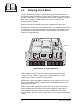
4.6 Motherboard
The motherboard is the large board in the upper chassis interconnecting the audio
processor, stereo generator, RF exciter, and metering boards. The motherboard
eliminates the need for a wiring harness, and provides input/output filtering, test
points, and modular customization.
Motherboard components are passive with the exception of the fan driver transistor,
power FET Q501.
With Normal-Bypass slide switch SW501, it is possible to bypass the audio
processor, connecting the left and right audio inputs directly to the inputs of the
stereo generator.
In the BYPASS position, the pre-emphasis circuits and the filters that protect the
pilot and stereo subcarrier are bypassed. As a result, the occupied bandwidth
specifications of the transmitter could be compromised. The 15–Hz high-pass
filters are also bypassed which may mean that modulation with frequencies
below 10 Hz could cause the frequency synthesizer to unlock.
CAUTION
If the audio source is already processed, and further processing is not desired, use
the Normal mode instead of Bypass and turn the Processing control on the front
panel to “0”.
If it is necessary to provide resistive terminations at the audio inputs (either line-
to-line or line-to-ground), you may place resistors directly into the 8–pin DIP
socket, A501, located between the XLR input connectors. See Illustration 6–9 and
accompanying schematic for the socket pin-out.