
Specifications


4–10
FM500 User's Manual
i
n
q
u
e
s
t
o
m
o
n
d
o
,
f
o
r
s
e
,
u
n
o
s
i
d
i
c
e
s
e
d
i
c
i
a
m
o
c
h
e
m
a
s
c
r
i
v
e
n
d
o
c
o
n
i
n
q
u
e
s
t
o
m
o
n
d
o
,
f
o
r
s
e
,
u
n
o
s
i
d
i
c
e
s
e
d
i
c
i
a
m
o
c
h
e
m
a
s
c
r
i
v
e
n
d
o
c
o
n
m
a
s
c
r
i
v
e
n
d
o
c
o
n
i
n
q
u
e
s
t
o
m
o
n
d
o
,
f
o
r
s
e
,
u
n
o
s
i
d
i
c
e
s
e
d
i
c
i
a
m
o
c
h
e
m
a
s
c
r
i
v
e
n
d
o
c
o
n
m
a
s
c
r
i
v
e
n
d
o
c
o
n
in
q
u
e
s
t
o
m
o
n
d
o
,
f
o
r
s
e
,
u
n
o
s
i
d
i
c
e
s
e
d
i
ci
a
m
o
c
h
e
m
a
s
c
r
i
v
e
n
d
o
c
o
n
s
e
d
i
c
i
a
m
o
c
h
e
m
a
s
c
r
i
v
e
n
d
o
c
o
n
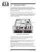
4.7 Display Circuit Board
The front-panel LEDs, the numeric display, the slide switches, and the processing
and RF level controls are mounted on the display circuit board. To access the
component side of the board, remove the front panel by removing 12 screws. The
board contains circuits for the digital panel meter, modulation peak detector, and
LED display drivers, as well as indicators and switches mentioned above.
Illustration 6–10 and accompanying schematic complement this discussion.
Left and right audio from input stages of the audio processor board (just after the
Input Gain attenuator) go to the L VU and R VU input on the display board. Peak
rectifiers U601A and U601B drive the left and right Audio Input displays. The LED
driver gives a 3 dB per step display. The lowest step of the display driver is not
used; rather a red LOW indicator lights when audio is below the level of the second
step. Transistors Q601 and Q602 divert current from the LOW LEDs when any
other LED of the display is lit.
Resolution of the linear displays, High Band, Wide Band, and Modulation, has been
improved using dither enhancement. With dither, the brightness of the LED is
controlled by proximity of the input voltage relative to its voltage threshold. The
effect is a smooth transition from step to step as input voltage is changed. U606A,
U606B, and associated components comprise the dither generator. Dither output
is a triangular wave.
Composite stereo (or mono) is full-wave detected by diodes D605 and D606. U607,
U613, Q603, and Q604 are components of a peak sample-and-hold circuit.
Oscillator, U609F, supplies a low-frequency square wave to the Fault indicators,
causing them to flash on and off.
Digital multimeter inputs are selected with push buttons located to the right of
the multimeter menu. Signals from the push buttons are conditioned by U609A
and U609B. U610 is an up/down counter. Binary input to U611 from U610 selects
a green menu indicator light, and lights the appropriate decimal point on the
numeric readout. The binary lines also go to analog data selectors on the ALC/
metering board.
Processing control, R650, is part of the audio processor. (See section 4.2.)
The DPM IN and DPM REF lines are analog and reference voltage inputs to digital
multimeter IC U612. They originate from analog data selectors on the ALC/
metering board.