
Specifications


4–11
Principles of Operation
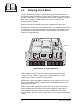
4.8 Voltage Regulator Circuit Board
The voltage regulator board is the longer of two boards mounted under the chassis
toward the front of the unit. It has switch-mode voltage regulators to provide +12,
–12, and 24 volts. It also contains the program detection and automatic carrier
control circuits.
Illustration 6–11 and accompanying schematic complement this discussion.
U703E and U703F convert a 38 kHz sine wave from the stereo generator into a
synchronization pulse. In the transmitter, synchronization is not used, thus D709
is omitted.
U704 and U705 form a 24 volt switching regulator running at about 35 kHz. U704
is used as a pulse-width modulator; U705 is a high-side driver for MOSFET switch
Q701. Supply voltage for the two IC’s (approximately 15.5 volts) comes from linear
regulator DZ702/Q705. Bootstrap voltage, provided by D710 and C714, allows the
gate voltage of Q701 to swing about 15 volts above the source when Q701 is turned
on. Current through the FET is sensed by R738 and R738A. If the voltage
between pin 5 and 6 of U705 exceeds 0.23 volts on a current fault, drive to Q701 is
turned off. Turn-off happens cycle by cycle. The speed of the turn-off is set by
C713.
U706 is a switching regulator for both +12 volts and –12 volts. It runs at about 52
kHz. Energy for –12 volts is taken from inductor L702 during the off portion of
the switching cycle. The –12 volts tracks the +12 volts within a few tenths of a
volt. There will be no –12 volts until current is drawn from the +12 volts.
Q702, Q703, and Q704 form an active filter and switch, supplying DC voltage to
the RF driver, when the Carrier switch is on.
The program detection circuit is made up of U701 and U702. U701A and U701D
and associated circuitry discriminate between normal program material and white
noise (such as might be present from a studio-transmitter link during program
failure) or silence. U701A and surrounding components form a band-pass filter
with a Q of 3 tuned to about 5 kHz. U701D is a first-order low-pass filter. Red and
green LEDs on the board indicate the presence or absence of program determined
by the balance of the detected signals from the two filters. U702 and U701C form a
count-down timer. The time between a program fault and shutdown is selected by
jumpering pins on header JP701. For times, see section 5.7. The times are
proportional to the value of R721 (that is, times can be doubled by doubling the
value of R721).