
Specifications


4–12
FM500 User's Manual
i
n
q
u
e
s
t
o
m
o
n
d
o
,
f
o
r
s
e
,
u
n
o
s
i
d
i
c
e
s
e
d
i
c
i
a
m
o
c
h
e
m
a
s
c
r
i
v
e
n
d
o
c
o
n
i
n
q
u
e
s
t
o
m
o
n
d
o
,
f
o
r
s
e
,
u
n
o
s
i
d
i
c
e
s
e
d
i
c
i
a
m
o
c
h
e
m
a
s
c
r
i
v
e
n
d
o
c
o
n
m
a
s
c
r
i
v
e
n
d
o
c
o
n
i
n
q
u
e
s
t
o
m
o
n
d
o
,
f
o
r
s
e
,
u
n
o
s
i
d
i
c
e
s
e
d
i
c
i
a
m
o
c
h
e
m
a
s
c
r
i
v
e
n
d
o
c
o
n
m
a
s
c
r
i
v
e
n
d
o
c
o
n
in
q
u
e
s
t
o
m
o
n
d
o
,
f
o
r
s
e
,
u
n
o
s
i
d
i
c
e
s
e
d
i
ci
a
m
o
c
h
e
m
a
s
c
r
i
v
e
n
d
o
c
o
n
s
e
d
i
c
i
a
m
o
c
h
e
m
a
s
c
r
i
v
e
n
d
o
c
o
n
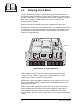
4.9 Power Regulator Circuit Boards
The power regulator boards are the two boards mounted under the chassis on
either side of a pair of 15,000 µf filter capacitors toward the front of the unit. Each
board has the switch-mode voltage regulator for a RF power amplifier, and
circuitry for PA supply current metering.
Illustration 6–12 and accompanying schematic complement this discussion.
Diode D804, in series with the battery input, together with the AC-supply diode
bridge, provides diode OR-ing of the AC and DC supplies.
U801 and U802 form a switching regulator running at about 35 kHz. U801 is used
as a pulse-width modulator; U802 is a high-side driver for MOSFET switch Q801.
Power for the two IC’s comes from the 24 volt supply voltage for the RF driver
(available when the Carrier switch is on). The voltage is controlled at 16 volts by
zener diode DZ801. Bootstrap voltage provided by D802 and C809 allows the gate
voltage of Q801 to swing about 16 volts above the source when Q801 is turned on.
Current through the FET is sensed by R812 and R812A. If the voltage from pin 5
to 6 of U802 exceeds 0.23 volts on a current fault, drive to Q801 is turned off. This
happens on a cycle-by-cycle basis. The speed of the turnoff is set by C805.
In the transmitter, synchronization is not used, thus D801 is omitted.
U803 and Q802 are used in a circuit to convert the current that flows through
metering shunt, R819, into a current source at the collector of Q803. Forty
millivolts is developed across R819 for each amp of supply current (.04 ohms x 1
amp). Q803 is biased by U803 to produce the same voltage across R816. The
collector current of Q803 is the same (minus base current) as that flowing through
R822 resulting in 40 microamperes per amp of shunt current. R405 on the
metering board converts Q803 collector current to 0.1 volt per amp of shunt
current (.04 ma X 2.49 k). (See section 5.4.)
4.10 RF Driver
The RF Driver module is mounted next to the heat sinks on the bottom of the RF
Amplifier/Combiner sub chassis. The driver amplifies the approximate 20
milliwatts from the frequency synthesizer to about 15 watts to drive the RF power
amplifiers. A CA2832 hybrid, high-gain, wideband amplifier, operating at about 20
volts, provides about one watt of drive to a single MRF137 MOSFET amplifier. The
MRF137 stage operates from a supply voltage of approximately 15 to 16 volts.
The circuit board has components for input and output coupling and for power
supply filtering.