
Specifications


4–15
Principles of Operation
Generally, the voltage is around 0.5 volt DC for tuning 88.1 MHz, and from 5.5 to
6.5 volts DC for tuning 107.9 MHz. The 10.7 MHz IF frequency comes out of the
tuner module on pin 5 and is coupled into the first filter FL1; passes through FL1
and into the IF decoder system of IC LM1865 (U1). The FL1 filter sets the
bandwidth or everything outside of the bandwidth depending on the filter that is
selected. It could be a bandwidth of 180 kHz where everything outside of that is
filtered out depending on the filter characteristics. A second filter (F3) is available
when the signal has a great amount of interference from an adjacent signal. In
such a case, remove the jumper cap that is in the F3 position, then remove the
ceramic filter that is in the F4 storage position and place it into the F3 position.
Then the signal goes to a buffer gain stage at pin 1 of LM1865 (U1). From there
the signal passes through F2, which is a second filter for further removal of
unwanted products, and then it goes on to the IF of that chip. The quadrature coil
L4 is tuned to 10.7 MHz as per calibration procedures. This results in a low
distortion of around 0.2 to 0.3% on the audio. The audio, still a composite at this
point, will come out of pin 15 of that IC (U1) and go to the first buffer U9. Then it
goes through a compensation network R54 and C26, and on to the stereo decoder
chip at pin 2 of U5.
When a stereo signal is present, Led 1 illuminates which indicates that left and
right audio is available. Then the stereo signals go to gain stages U6A and U6B and
out to the RCA jacks on the back of the cabinet. These can be used for off-air
monitoring of the audio signal. Incoming frequency can be monitored from the
frequency monitor BNC jack on the back. The stereo buffer U9, stereo decoder U5,
and gain stages U6A and U6B have no effect on the signal that goes through the
transmitter. This section along with the composite signal coming out of pin 15 of
LM1865 (U1) is totally separate from the transmitter section.
Stereo
Generator
FM500
FM BROADCAST TRANSMITTER
®
Power
Carrier
Modulation
Fault
Stereo
Mono RF Output
ProcessingInput Gain
Wide Band
High Band
Audio Input
High
Low
2
-6
-12
-18
2
+6 dB
+12 dB
10
20
Expand
Compress
RF Power
SWR
ALC
PA DC Volts
PA DC Amps
PA Temperature
Supply DC Volts
Voltmeter
SWR
Lock
Input
PA DC
PA Temp
Over
100
90
80
70
60
50
40
30
20
Pilot
RF IN
Receiver Module
(option)
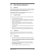
Illustration 4–6 Receiver Board (optional)