
Specifications


5–3
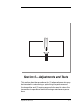
Adjustments and Tests
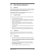
5.2 Stereo Generator Adjustments
5.2.1 Separation
Feed a 400 Hz sine wave into one channel for at least 70% modulation. Observe the
classic single-channel composite stereo waveform at TP1 on the RF Exciter circuit
board. Adjust the Separation control for a straight centerline.
Since proper adjustment of this control coincides with best stereo separation, use
an FM monitor to make or confirm the adjustment.
5.2.2 Composite Output
Adjust the composite output with a modultion monitor following the steps below:
1. Set the Stereo-Mono switch to Mono.
2. Check that the setting of the Modulation compensation control, R17 on the
RF Exciter circuit board, falls within the range specified for the frequency of
operation. (See section 2.3.1.)
3. Feed a sine wave signal of about 2.5 kHz into the left channel at a level
sufficient to put the wideband gain-reduction indicator somewhere in the
middle of its range.
4. Set the Composite level control to produce 90% modulation as indicated on
an FM monitor.
5. Apply pink noise or program material to the audio inputs and confirm, on
both Mono and Stereo, that modulation peaks are between 95% and 100%.
5.2.3 19 kHz Level
Adjust the 19 kHz pilot for 9% modulation as indicated on an FM modulation
monitor. (The composite output should be set first, since it follows the 19 kHz
Level control.)
5.2.4 19 kHz Phase
1. Apply a 400 Hz audio signal to the left channel for at least 70% modulation.
2. Look at the composite stereo signal at TP301 on the RF Exciter circuit board
with an oscilloscope, expanding the display to view the 19 kHz component on
the horizontal centerline.
3. Switch the audio to the right-channel input. When the 19 kHz Phase is
properly adjusted, the amplitude of the 19 kHz will remain constant when
switching between left and right.
4. Recheck the separation adjustment as described in section 5.2.1.