Models: Micro-Tech 600, 1200 & 2400 Micro-Tech 601, 1201 & 2401 Some models may be exported under the name Amcron.® © 2001 by Crown Audio, Inc., P.O. Box 1000, Elkhart, IN 46515-1000 U.S.A. Telephone: 219-294-8000. Fax: 219-294-8329. Trademark Notice: Grounded Bridge™ is a trademark and Amcron®, Crown ®, Micro-Tech and ODEP are registered trademarks of Crown International, Inc. Other trademarks are the property of their respective owners.
3 YEAR THREE YEAR FULL WARRANTY 3 YEAR WORLDWIDE NORTH AMERICA SUMMARY OF WARRANTY The Crown Audio Division of Crown International, Inc., 1718 West Mishawaka Road, Elkhart, Indiana 46517-4095 U.S.A.
The information furnished in this manual does not include all of the details of design, production, or variations of the equipment. Nor does it cover every possible situation which may arise during installation, operation or maintenance. If your unit bears the name “Amcron,” please substitute it for the name “Crown” in this manual. If you need special assistance beyond the scope of this manual, please contact our Technical Support Group. Crown Technical Support Group Plant 2 SW, 1718 W. Mishawaka Rd.
Micro-Tech 600/1200/2400 Power Amplifiers Important Safety Instructions 1) Read these instructions. 2) Keep these instructions. 3) Heed all warnings. 4) Follow all instructions. 5) Do not use this apparatus near water. 6) Clean only with a dry cloth. 7) Do not block any ventilation openings. Install in accordance with the manufacturer’s instructions. 8) Do not install near any heat sources such as radiators, heat registers, stoves, or other apparatus that produce heat.
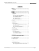
Micro-Tech 600/1200/2400 Power Amplifiers CONTENTS 1 Welcome ........................................................................... 7 1.1 Unpacking ................................................................. 7 1.2 Features ..................................................................... 7 2 Facilities ........................................................................... 8 3 Installation ..................................................................... 3.1 Mounting ................
Micro-Tech 600/1200/2400 Power Amplifiers ILLUSTRATIONS 1.1 2.1 2.2 3.1 3.2 3.3 3.4 3.5 3.6 3.7 3.8 3.9 3.10 3.11 3.12 3.13 3.14 3.15 3.16 4.1 4.2 5.1 6.1 6.2 6.3 6.4 6.5 6.6 6.7 6.8 6.9 6.10 6.11 6.12 6.13 7.1 7.2 7.3 8.1 8.2 Page 6 Micro-Tech Amplifier ................................................................... 7 Front Facilities ............................................................................ 8 Rear Facilities ........................................................................
Micro-Tech 600/1200/2400 Power Amplifiers Fig. 1.1 Micro-Tech Amplifier 1 Welcome Congratulations on your purchase of a Micro-Tech® professional power amplifier. Crown’s Micro-Tech 600, 1200 and 2400 are the original industry standards for touring amplifiers. Micro-Tech amplifiers are known around the world as a the benchmark for high-density, ultra-pure power in a compact, lightweight package.
Micro-Tech 600/1200/2400 Power Amplifiers Fig. 2.1 Front Facilities 2 Facilities A. Filter Grille This metal grille supports and protects the dust filter (B). To clean the dust filter, detach the grille by removing the three screws that hold it in place. on, AC power is available and the low-voltage power supply and fan are operational (see Section 4.2). E. Power Switch The dust filter removes large particles from the air drawn by the cooling fan.
Micro-Tech 600/1200/2400 Power Amplifiers BRIDGE-MONO WIRING – PUSH TO RESET CH-2 5 F RED TERMINALS ONLY. (CH-1 IS POSITIVE.) CH-1 BRIDGE MONO CAUTION: TURN OFF AMPLIFIER BEFORE CHANGING THIS SWITCH! G H – GND 10 1 12 INPUT GAIN RING SLEEVE I J 8 LIFT 9 2 INPUT GROUND LIFT 11 0 + TIP 7 3 9 2 BALANCED INPUT WIRING 5 6 4 8 3 WARNING: TO REDUCE THE RISK OF FIRE OR ELECTRIC SHOCK DO NOT EXPOSE THIS EQUIPMENT TO RAIN OR MOISTURE.
Micro-Tech 600/1200/2400 Power Amplifiers 3 Installation 3.1 Mounting Micro-Tech amplifiers are designed for standard 19-inch (48.3-cm) rack mounting or stacking without a cabinet. In a rack, it is best to mount units directly on top of each other. This provides the most efficient air flow and support. If the rack will be transported, we recommend that you provide support for the amplifier’s back panel or secure it to the rack to help support the unit’s weight. Fig. 3.1 Mounting Dimensions 3.
Micro-Tech 600/1200/2400 Power Amplifiers the rack so it blows outside air into the space between the door and the front of the amplifiers. This will pressurize the “chimney” behind the door (Figure 3.3, Option 1). The blower should not blow air into or take air out of the space behind the amplifiers. For racks without a front door, you can evacuate the rack by mounting the blower at the top of the rack so air blows out the back (Figure 3.3, Option 2).
Micro-Tech 600/1200/2400 Power Amplifiers CAUTION: In Stereo mode, never tie the amplifier’s outputs directly together, and never parallel them with the output of another amplifier. Such connections do not increase the output power and may activate the protection circuitry to prevent overheating. 3.3.2 Bridge-Mono Operation Bridge-Mono mode is used to drive loads with a total impedance of at least 4 ohms (see Section 3.3.3 if the load is less than 4 ohms).
Micro-Tech 600/1200/2400 Power Amplifiers CAUTION: Only connect balanced equipment (meters, switches, etc.) to the Bridge-Mono output. Both sides of the line must be isolated from the input grounds or oscillations may occur. 3.3.3 Parallel-Mono Operation Parallel-Mono mode is used to drive loads with a total impedance of less than 4 ohms (see Section 3.3.2 if the load is 4 ohms or more). Installing the amplifier in Parallel-Mono mode is very different from the other modes and requires special attention.
Micro-Tech 600/1200/2400 Power Amplifiers 3.3.4 Input Connection The balanced phone jack inputs have a nominal impedance of 20 K ohms (10 K ohms with unbalanced wiring) and will accept the line-level output of most devices. Three-pin female XLR connectors are also available on the optional MT-XLR accessory and balanced barrier block connectors are available on the optional MT-BB accessory (see Section 8.2).
Micro-Tech 600/1200/2400 Power Amplifiers SOLVING INPUT PROBLEMS Sometimes large subsonic (subaudible) frequencies are present in the input signal. These can damage loudspeakers by overloading or overheating them. To attenuate such frequencies, place a capacitor in series with the input signal line. The graph in Figure 3.10 shows some possible capacitor values and how they affect frequency response. Use only low-leakage paper, mylar or tantalum capacitors. 910 Ω + A + .
Micro-Tech 600/1200/2400 Power Amplifiers rent by minimizing the cross-sectional area between conductors that could bisect the magnetic field. excellent damping factor can easily be negated by using insufficient loudspeaker cables. Ground loops will also occur when the input and output grounds are tied together. DO NOT CONNECT THE INPUT AND OUTPUT GROUNDS TOGETHER. Tying the input and output grounds together can also cause feedback oscillation from the load current flowing in the loop.
Micro-Tech 600/1200/2400 Power Amplifiers 1. Note the load resistance of the loudspeakers connected to each channel of the amplifier. Mark this value on the “Load Resistance” line of the nomograph. 2. Select an acceptable damping factor and mark it on the “Damping Factor” line. Your amplifier can provide an excellent damping factor of 1,000 from 10 to 400 Hz in Stereo mode with an 8 ohm load. In contrast, typical damping factors are 50 or lower at these frequencies.
Micro-Tech 600/1200/2400 Power Amplifiers 3.3.6 Additional Load Protection Micro-Tech amplifiers can deliver very high power levels, so it’s a good idea to add some protection if its not already built into your loudspeakers. Loudpseakers are subject to thermal damage from sustained overpowering and mechanical damage from large transient voltages. In both cases, fuses may be used to protect your loudspeakers. Thermal protection and voltage protection require different types of fuses.
Micro-Tech 600/1200/2400 Power Amplifiers 4 Operation 4.1 Precautions Although your amplifier is protected from internal and external faults, you should still take the following precautions for optimum perfromance and safety: 1. Improper wiring for the Stereo, Bridge-Mono and Parallel-Mono modes can result in serious operating difficulties (see Section 3.3). 2. WARNING: Do not change the position of the stereo/mono switch unless the amplifier is first turned off. 3.
Micro-Tech 600/1200/2400 Power Amplifiers of delivering under the present conditions, ODEP immediately limits the drive level until it falls within the SOA. Limiting is proportional and kept to an absolute minimum—only what is required to prevent output transistor damage. Under normal conditions, no limiting is required and ODEP is transparent to the audio signal. This level of protection enables Crown to increase output efficiency to never-before-achieved levels while greatly increasing reliability.
Micro-Tech 600/1200/2400 Power Amplifiers 4.4 Controls To change the input sensitivity: The power switch is located on the front panel so you can easily turn the amplifier on or off. If you ever need to make any wiring or installation changes, don’t forget to disconnect the power cord. Please follow these steps when first turning on your amplifier: 1. Turn off the amplifier and disconnect its power cord from the AC power source. 2. Remove the back panel cover plate (or input connector accessory). 2.
Micro-Tech 600/1200/2400 Power Amplifiers 5 Technical Information 5.1 Overview Micro-Tech amplifiers incorporate several technological advancements including real-time computer simulation of output transistor stress, low-stress output stages and an advanced heat sink embodiment. Custom circuitry is incorporated to limit temperature and current to safe levels making it highly reliable and tolerant of faults.
Micro-Tech 600/1200/2400 Power Amplifiers Fig. 5.
Micro-Tech 600/1200/2400 Power Amplifiers with their push-pull effect through the bias servo Q318, drive the fully complementary output stage. The bias servo Q318 is thermally coupled to the heat sink and sets the quiescent bias current in the output stage to lower the distortion in the crossover region of the output signal. D301, D302, D303, and D304 remove the charge on the unused portion of the output stage based on the polarity of the output signal.
Micro-Tech 600/1200/2400 Power Amplifiers 6 Specifications The following applies to units in Stereo mode with with both channels driven into 8 ohm loads and an input sensitivity of 26 dB unless otherwise specified. Standard 1 kHz Power: refers to maximum average power in watts at 1 kHz with 0.1% THD. Full Bandwidth Power: refers to maximum average power in watts from 20 Hz to 20 kHz with 0.1% THD. 120 VAC, 60 Hz Units: refers to amplifiers with dedicated transformers for 120 VAC, 60 Hz power mains.
Micro-Tech 600/1200/2400 Power Amplifiers Controls Power: A front panel rocker switch used to turn the amplifier on and off. Level: A back panel rotary potentiometer for each channel used to control the output level. Stereo/Mono: A three-position back panel switch used to select Stereo, Bridge-Mono or Parallel-Mono mode. Sensitivity: A three-position switch inside the back cover plate used to select the input sensitivity for both channels: 0.775 volts or 1.
Micro-Tech 600/1200/2400 Power Amplifiers Crown specifications are guaranteed for three years. In an effort to provide you with as much information as possible about the high power-producing capabilities of your amplifier, we have created the following power matrices. Minimum Power Specifications Crown’s minimum power specifications represent the absolute smallest amount of output power you can expect from your amplifier when it is driven to full output under the given conditions.
Micro-Tech 600/1200/2400 Power Amplifiers Stereo/Mono Mode 120 VAC, 60 Hz Units Stereo (both channels driven) Bridge-Mono (balanced output) Parallel-Mono Stereo International Units (both channels driven) Bridge-Mono (balanced output) Parallel-Mono Maximum Average FTC Continuous Average Load (Ohms) AC Mains Micro-Tech 1200 – Minimum Guaranteed Power (Watts) 0.1% THD (See note 1) 1 kHz 20Hz-20kHz 1 kHz 2 675 585 660 4 480 450 8 310 295 0.1% THD (See note 2) 0.
Micro-Tech 600/1200/2400 Power Amplifiers Maximum Power Specifications Crown’s maximum power specifications represent the largest amount of output power you can expect from your amplifier when it is driven to full output under the given conditions. These specifications can be used to prevent loudspeaker and hearing damage. The maximum power matrices include specifications for single cycle and 40 millisecond burst sine waves.
Micro-Tech 600/1200/2400 Power Amplifiers Stereo/Mono Mode 120 VAC, 60 Hz Units Stereo (both channels driven) Bridge-Mono (balanced output) Parallel-Mono Stereo International Units (both channels driven) Bridge-Mono (balanced output) Parallel-Mono Load (Ohms) AC Mains Micro-Tech 1200 – Maximum Power (Watts) Single Cycle Tone Burst 40 Millisecond Tone Burst 0.05% Distortion (See note 1) 0.
Micro-Tech 600/1200/2400 Power Amplifiers +2 +1 0 –1 –2 8 ohm 4 ohm –3 2 ohm 1 watt dB –4 –5 –6 –7 10 100 1K 10 K 100 K FREQUENCY (Hz) Fig. 6.7 Typical Frequency Response 1400 1200 1000 800 600 400 8 ohm 200 100 0 100 20 1K 10 K 20 K FREQUENCY (Hz) Fig. 6.8 Typical Damping Factor 504.0 126.8 MILLIOHMS 6 dB 31.8 8.0 2.0 10 100 1K 10 K 100 K FREQUENCY (Hz) Fig. 6.
Micro-Tech 600/1200/2400 Power Amplifiers TEF ® Measurement +45˚ 0˚ –45˚ 100 1K 10 K 20 K FREQUENCY (Hz) Fig. 6.10 Typical Phase Response TEF ® Measurement –45 –51 –57 –63 dB –69 –75 –81 100 1K 10 K 20 K FREQUENCY (Hz) Fig. 6.
Micro-Tech 600/1200/2400 Power Amplifiers TEF ® Measurement –66 –72 –78 –84 dB –90 –96 –102 100 1K 10 K 20 K FREQUENCY (Hz) Fig. 6.12 Typical Crosstalk for the Micro-Tech 1200 TEF ® Measurement –60 –66 –72 –78 dB –84 –90 –96 100 1K 10 K 20 K FREQUENCY (Hz) Fig. 6.
Micro-Tech 600/1200/2400 Power Amplifiers 7 AC Power Draw and Thermal Dissipation This section provides detailed information about the amount of power and current drawn from the AC mains by Micro-Tech amplifiers and the amount of heat produced under various conditions. The calculations presented here are intended to provide a realistic and reliable depiction of the amplifiers.
Micro-Tech 600/1200/2400 Power Amplifiers Micro-Tech 1200 L O A D 8 Ohm Stereo / 16 Ohm Bridge-Mono / 4 Ohm Parallel-Mono 4 Ohm Stereo / 8 Ohm Bridge-Mono / 2 Ohm Parallel-Mono 2 Ohm Stereo / 4 Ohm Bridge-Mono / 1 Ohm Parallel-Mono Duty Cycle AC Mains Power Draw (Watts) 50% 560 6.7 40% 465 5.6 30% 370 20% 10% Current Draw (Amps) Thermal Dissipation 100-120 V 220-240 V btu/hr kcal/hr AC Mains Power Draw (Watts) 3.0 845 215 830 10.0 2.5 730 185 680 8.2 4.4 2.
Micro-Tech 600/1200/2400 Power Amplifiers 8 Accessories 8.1 Cooling Fan Options Every Micro-Tech amplifier has a built-in high-velocity fan that provides optimum cooling. Two optional replacement fan blades are available for special cooling requirements. Crown part C 6594-3 is a quieter, lowvelocity fan blade that in many cases can provide adequate cooling.
Micro-Tech 600/1200/2400 Power Amplifiers 9 Service This unit has very sophisticated circuitry which should only be serviced by a fully trained technician. This is one reason why each unit bears the following label: CAUTION: To prevent electric shock, do not remove covers. No user serviceable parts inside. Refer servicing to a qualified technician. Factory Service Shipping Instructions: 1.
Crown Factory Service Information Shipping Address: Crown Audio, Inc., Factory Service, Plant 2 SW, 1718 W. Mishawaka Rd.