
Technical information

Macro-Tech 3600VZ Power Amplifier
Page 13
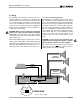
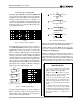
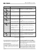
Fig. 3.6 Parallel-Mono Wiring
PARALLEL-MONO MODE
Macro-Tech 3600VZ
CH-2 OUTPUT CH-1 OUTPUT
INPUT INPUT
CH-2 CH-1
PUSH
FX
PUSH
CH-2 CH-1INPUTS
(MONO)
STEREO
BRIDGE
MONO
PARALLEL
MONO
STEREO
BRIDGE
MONO
PARALLEL
MONO
CAUTION:
TURN OFF AMPLIFIER
BEFORE CHANGING THIS SWITCH!
MIXER
USE ONLY CHANNEL 1 INPUT
LOUDSPEAKER
DO NOT USE
CHANNEL 2
INPUTS.
ADD A 14 GAUGE
(OR LARGER)
JUMPER BETWEEN
THE CHANNEL 1
AND 2 RED
BINDING POSTS.
–
+
3.3.3 Parallel-Mono Operation
Parallel-Mono mode is used to drive loads with a total
impedance of less than 4 ohms. (See Bridge-Mono if
the load is 4 ohms or greater.) Installing the amplifier in
Parallel-Mono mode is very different from the other
modes and requires special attention.
CAUTION: Do not attempt to operate in Stereo or
Bridge-Mono mode until the Parallel-Mono jumper
is first removed. Failure to do so will definitely
cause inefficient operation, high distortion and ex-
cessive heating.
To put the amplifier in Parallel-Mono mode, first turn it
off, then slide the Stereo/Mono switch to the left (as you
face the back). Connect the input signal to Channel 1
only. DO NOT USE THE CHANNEL 2 INPUT or the sig-
nal level and quality may degrade greatly. Turn off the
Channel 2 Level control (full counterclockwise).
Note: It is normal for the IOC indicator of Channel 2 to
stay on in Parallel-Mono mode.
The input jack and Level control of Channel 2 are not
defeated in Parallel-Mono mode. Any signal fed into
Channel 2 may work against and add to or distort the
signal in Channel 1.
Install a jumper wire between the red binding posts of
both Channel 1 and 2 that is at least 14 gauge in size.
Then, connect the load to the output of Channel 1 as
shown in Figure 3.6. The positive lead from the load
connects to the red binding post of Channel 1 and the
negative lead from the load connects to the black bind-
ing post of Channel 1.
CAUTION: Remove the jumper wire before chang-
ing to any mode except Parallel-Mono.