
Technical information

Page 19Reference Manual
Macro-Tech
®
24x6 & 36x12 Power Amplifiers
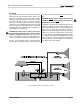
the drive level. Second, ODEP data is fed to the back
panel PIP connector so advanced PIP modules like the
IQ–P.I.P.–SMT can use it to monitor and control the am-
plifier.
With ODEP, the show keeps going because you get the
maximum power with the maximum protection.
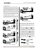
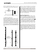
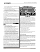
4.3.2 Standby Mode
At the heart of the protection systems is the standby
mode which removes power from the high-voltage sup-
plies to protect the amplifier and connected loads. The
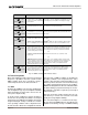
standby mode can be identified using the indicator
table in Figure 4.2.
Standby mode can be activated in several situations.
First, if dangerous subsonic frequencies or direct cur-
rent (DC) is detected in the amplifier’s output, the unit
will activate its DC/low-frequency protection circuitry
and put the affected channels in standby. This protects
the loads and prevent oscillations. The unit resumes
normal operation as soon as the amplifier no longer
detects dangerous low frequency or DC output. Al-
though it is extremely unlikely that you will ever activate
the amplifier’s DC/low-frequency protection system,
improper source materials such as subsonic square
waves or input overloads that result in excessively
clipped input signals can activate this system.
The amplifier’s fault protection system will put an am-
plifier channel in standby mode in rare situations where
heavy common-mode current is detected in the
channel’s output. The amplifier should never output
heavy common-mode current unless its circuitry is dam-
aged in some way, and putting a channel in standby
mode helps to prevent further damage.
The amplifier’s transformer thermal protection cir-
cuitry is activated in very unusual circumstances where
the unit’s transformer temperature rises to unsafe lev-
els. Under these abnormal conditions, the amplifier will
put the channel of the affected transformer in standby
mode. The amplifier will return to normal operation after
the transformer cools to a safe temperature. (For more
information on transformer thermal protection, refer to
the following section.)
4.3.3 Transformer Thermal Protection
All Macro-Tech amplifiers have transformer thermal pro-
tection. It protects the power supplies from damage
under the rare conditions of transformer temperatures
rising too high. A thermal switch embedded in each
transformer removes power to the channel if there is
excessive heat. The switch automatically resets when
the transformer cools to a safe temperature.
It is very unlikely that you will ever see a Macro-Tech
amplifier activate transformer thermal protection as long
as it is operated within rated conditions (see Section 6,
Specifications
). One reason is that ODEP keeps the
amplifier working under very severe conditions. Even
so, higher than rated output levels, excessively low im-
pedance loads and unreasonably high input signals
can generate more heat in the transformer than in the
output devices. These conditions can overheat the
transformer and activate its protection system.
Macro-Tech amplifiers are designed to keep working
under conditions where other amplifiers would fail. But
even when its limits are exceeded, it will still protect
itself—and your investment—from damage.
4.3.4 Circuit Breakers
The power supplies are protected by circuit breakers. With
rated loads and output levels, the circuit breakers should
only shut down the amplifier in the rare instance of a cata-
strophic failure. Other protection systems like ODEP keep
the amplifier
operational under most other severe condi-
tions. The circuit breakers can also shut down the amplifier
in cases where extremely low-impedance loads and high
output levels result in current draw that exceeds their rat-
ing. Again, this should only be possible when operating
outside rated conditions
, like when the amplifier is used to
drive a 1-ohm load in Stereo mode, or when a signal over-
loads the input and is clipped severely.
Macro-Tech amplifiers do not trip their breakers unless
something is wrong. If a breaker trips, try to identify and
correct the problem before resetting the breakers with the
back panel Reset switches. If the problem persists, refer
the unit to a qualified technician.
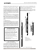
4.4 Controls
The Enable switch is located on the front panel so you
can easily turn the amplifier on or off. If you ever need to
make any wiring or installation changes don’t forget to
disconnect the power cord. The six steps listed next
should be followed whenever you turn on the amplifier:
1. Turn down the level of your audio source. For
example, set your master mixer’s volume to –¥.
2. Turn down the level controls of the amplifier (if they
are not already down).
3. Turn on the Enable switch. The Enable indicator
beside the switch should glow. During the four
second mute delay which immediately follows, the
Signal/IOC indicators will flash unpredictably and
the ODEP LEDs will stay off. After the mute delay,
the ODEP indicators should come on with full
brilliance and the Signal/IOC indicators should