IQ-PIP-USP3/CN Reference Manual An IQ Network™ Programmable Input Processor with TCP/IQ and CobraNet ™ Connectivity, SmartAmp ™ Features and Load Supervision for Crown PIP2™ -Compatible Amplifiers. Obtaining Other Language Versions: To obtain information in another language about the use of this product, please contact your local Crown Distributor. If you need assistance locating your local distributor, please contact Crown at 574-294-8000.
IQ-PIP-USP3/CN Crown Technical Support 1718 W. Mishawaka Rd., Elkhart, Indiana 46517 U.S.A. Phone: 800-342-6939 (North America, Puerto Rico and Virgin Islands) or 574-294-8200 Fax: 574-294-8301 Internet: http://www.crownaudio.com WATCH FOR THESE SYMBOLS. The exclamation point triangle is used to alert the user to important operating or maintenance instructions. The lightning bolt triangle is used to alert the user to the risk of electric shock.
IQ-PIP-USP3/CN Quick Install Procedure This procedure is provided for those who would like to install the IQ-PIP-USP3/CN in the shortest time possible and are already familiar with Crown’s IQ System and TCP/IQ. Less experienced installers or those wishing a full explanation of the installation procedure are encouraged to go to Section 3 where the full installation procedure is described. Prepare the amplifier: 1. Turn down the level controls of the amplifier and turn off the amplifier. 2.
IQ-PIP-USP3/CN Table of Contents FCC Compliance Notice .............................................................. 2 Quick Install Procedure ................................................................ 3 Illustrations .................................................................................. 6 1 Welcome ..................................................... 7 1.1 Unpacking ........................................................................ 7 1.2 How to Use This Manual ...................
IQ-PIP-USP3/CN Table of Contents (continued) 4.2.23 Sine Generator ........................................................ 22 4.2.24 Peak Voltage Limiter ............................................... 22 4.2.25 Average Power Limiter ............................................ 22 4.2.26 Clip Eliminator ........................................................ 23 4.2.27 Thermal Limiter ...................................................... 23 4.2.28 Limiter Tie .............................................
IQ-PIP-USP3/CN Illustrations 2.1 Front Panel Controls, Connectors and Indicators .................. 9 3.1 Installing the IQ-PIP-USP3/CN into the Amplifier ................. 11 4.1 Signal Flow Block Diagram .................................................... 14 4.2 Input Routing Screen ............................................................. 14 5.1 Input Wiring for the IQ-PIP-USP3/CN ................................... 28 5.2 A TCP/IQ Network ...........................................................
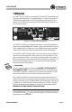
IQ-PIP-USP3/CN 1 Welcome The Crown® IQ-PIP-USP3/CN is a 3rd generation DSP-based PIP™ (Programmable Input Processor) input module for PIP2™ compatible amplifiers.* It connects the amplifier to a 100 Mb Ethernet network allowing it to be remotely controlled and monitored via IQ . In addition, the USP3/CN allows the transport of real-time digital audio via CobraNet™ over the same Ethernet network. Figure 1.
IQ-PIP-USP3/CN 1.2 How to Use This Manual This manual provides you with the necessary information to safely and correctly set up and operate your amplifier accessory. It does not cover every aspect of installation, setup or operation that might occur under every condition. For additional information, please consult Crown Tech Support, your system installer or retailer. We strongly recommend that you read all instructions, warnings and cautions contained in this manual.
IQ-PIP-USP3/CN 2 Controls, Indicators and Connectors A. Preset Indicator Signals the number of the current preset, if active, by flashing a series of flashes equal to the current preset number. See Section 4.1.2. B. Reset/Preset Switch Used to change presets, restore settings to factory default or restore all the presets to the factory defaults. During operations of the switch, the Data indicator flashes as an aid to the user. See Section 4.1.8. C.
IQ-PIP-USP3/CN 3 Installation Before beginning, please carefully note: CAUTION: STATIC ELECTRICITY MAY DAMAGE THE UNIT. Use caution when handling the unit. Carefully ground yourself BEFORE touching the unit. Avoided unnecessary touching the components or solder pads on the circuit board. It is best to handle the unit by its front panel only. The USP3/CN cannot be used in conjunction with a CT210 due to the amount of heat generated in the PIP Module cavity and the lack of a fan in the amplifier.
IQ-PIP-USP3/CN 3.3 Install the IQ-PIP-USP3/CN Into the Amplifier Carefully ground yourself to the chassis of the amplifier before installing the IQ-PIP-USP3/ CN. It is a good idea to maintain ground contact between yourself and the amplifier while inserting the module into the amplifier. Connect the PIP module to the amplifier. 1. Turn the PIP module upside down so the ribbon cable connectors located along the back edge on the underside of the module can be clearly seen (See Figure 3.1) 2.
IQ-PIP-USP3/CN 3.4 Install the Wiring 1. Using a standard CAT5 cable, connect the Primary CobraNet connector to a 100Mb port on the Ethernet switch that is used to form the CobraNet network. For more detail, see Section 4.1.3. If network redundancy is required, use a standard CAT5 cable to connect the Secondary CobraNet connector to a 100Mb port on the auxiliary CobraNet network. TCP/IQ control is also available over the CobraNet network using IQWic software. 2.
IQ-PIP-USP3/CN 4 Operation The USP3/CN provides a single plug solution for distribution of audio, control, and monitoring of the amplifier. A single CAT5 connection to a standard Fast Ethernet network used for CobraNet and TCP/IQ Control provides all of the necessary infrastructure wiring. The USP3/CN's SHARC DSP provides unequaled amounts of audio processing power for the amplifier's audio, all controllable from anywhere on the network using IQWic software.
IQ-PIP-USP3/CN Figure 4.1 shows the system block diagram. Figure 4.2 shows the input routing screen. Note that there are two pairs of "source" selectors - each allows selection of 1, 2 or the sum of both for both Analog and CobraNet Inputs. What goes into each of the input channel paths is one of a selection of four possible input configurations of the channel pair. Figure 4.1 Signal Flow Block Diagram Figure 4.
IQ-PIP-USP3/CN 4.1 Hardware 4.1.1 Data Indicator An amber Data indicator is provided on the front panel. It flashes whenever a command addressed to the IQ-PIP-USP3/CN is received. To assist with troubleshooting, an option that forces the data indicator to remain lit is available through the IQ software. Some Crown amplifiers also have a data indicator on their front panels. In these cases this indicator will light simultaneously as the PIP’s Data indicator. 4.1.
IQ-PIP-USP3/CN • Backup of the CobraNet Network audio: In the unlikely event of a loss of CobraNet audio to the USP3/CN, the module would automatically switch over to the Balanced Audio Inputs. • Emergency Override: If a hardwired emergency override signal would be required of the entire system, the USP3/CN would automatically sense the presence of the Emergency Override Signal at the Balanced Audio Inputs and switch to that signal.
IQ-PIP-USP3/CN The AUX port provides a power supply for the AUX input. This 15 VDC at 15 mA supply can be connected through a switch to the AUX input. This allows a simple switch closure to offset the aux input without the need of an external power supply. See Section 6.1 for details on using the AUX port. 4.1.8 Preset/Reset Switch The Preset/Reset switch is a recessed pushbutton located between the Data and Preset indicators. It is activated by a straightened paper clip or similar object.
IQ-PIP-USP3/CN 4.2.3 Input Signal Level Monitor The input signal level of each channel can be monitored. The measurement range is from +20dBu to -40dBu with 0.5dBu resolution. Each audio channel has the following monitors: • CobraNet Audio Input: The audio input level of the selected CobraNet audio channel. • Analog Audio Input: The audio input at the Balanced Audio Inputs of the USP3/CN's front panel. • Switched Audio Input: The audio input after the Input Audio Router. 4.2.
IQ-PIP-USP3/CN • CobraNet with Analog Backup: This allows the use of the Balanced Audio Inputs to be used as backup to the CobraNet audio should the network's audio be lost for any reason. In this mode, the USP3/CN will sense the loss of the CobraNet audio and will automatically switch to the chosen Balanced Audio Input until CobraNet network audio returns.
IQ-PIP-USP3/CN tem Error Window. The IQ software offers many options to further report errors, including audible alerts, printout, email, pager, serial port and fax. The following describes each error source. CLIP: The PIP can be configured to report if an excessive number of clip events occur in either amplifier channel. The clip events are consider an error if they exceed the defined count per the defined unit of time. The Count Control sets the maximum number of events before the error is reported.
IQ-PIP-USP3/CN Threshold: Sets the level, in dBu, above which the compressor begins to attenuate the input signal. This level corresponds to the input level meter reading. The compressor is “feed-forward,” meaning that the level detection point is located before the gain control stage. The range is from +16 dBu to – 40 dBu. Hysteresis: A “dead zone” that ensures a significant change before acting. The range is from 0 to 12 dB. Attack Time: Sets the attack time of the compressor.
IQ-PIP-USP3/CN 4.2.21 Delay Due to the nature of DSP processing, there is some inherent delay within the USP3/CN. These delays are: • Balanced Audio Input ADC: 312 µs • USP3/CN DSP Processing: 665 µs • Output DAC: 135 µs In addition to these unavoidable delays, additional delay can be added to each channel. Each channel is capable of 2.1 seconds of delay in 20.8 µs increments. 4.2.22 Noise Generator Each channel has an independent noise generator that allows noise to be mixed into the audio signal.
IQ-PIP-USP3/CN Enable: Enables or disables this limiter. Threshold: Sets the average power level, in watts, which the limiter will allow from the amplifier channel. The range is from 10 watts to 10,000 watts. This level should be set to the connected loudspeaker’s long-term power rating. Attack Time: Sets the attack time of the limiter. The attack time is defined as the time it takes the limiter to attenuate the output signal by 20 dB. The range is from 1 second to 30 seconds.
IQ-PIP-USP3/CN High Limit: Sets the upper bound above which the system will report a “high” error status. Low Limit: Sets the lower bound below which the system will report a “low” error status. Nominal Load Impedance: Sets the expected average impedance for the connected load. This value determines the output signal level required for the test. This parameter is also used by the average power limiter to determine the expected power threshold. (See Section 4.2.25).
IQ-PIP-USP3/CN Conductor Any CobraNet device can be configured to operate either as Network Conductor or a Performer: • Active Indicator: This indicator, viewable in IQ software, reports the present Conductor status of the device. If the indicator is ON, the unit is operating as the network Conductor. When OFF, the unit is operating as a Performer. • Priority: This parameter adjusts the priority level for becoming the Conductor.
IQ-PIP-USP3/CN 4.3.2 CobraNet Input Routing CobraNet input routing includes the following controls: CobraNet Receive Bundles The IQ-PIP-USP3/CN can receive four unique CobraNet Bundles (RxA, RxB, RxC, RxD). Each Bundle includes an “Active” indicator to indicate whether the particular Bundle is being actively transmitted onto the network. CobraNet Receive Channels Each CobraNet Bundle contains up to eight digital audio channels.
IQ-PIP-USP3/CN • Output Amplifier Audio: By sampling the actual output audio of the amplifer, CobraNet allows remote access and monitoring of each amplifier channel at the speaker! CobraNet extends the "Listen Bus" feature found on other PIP modules to any network user, allowing them to listen to the output of any networked amplifier from any location on the network.
IQ-PIP-USP3/CN 5 Audio Signal Wiring and Network Basics This section provides additional information about audio signal wiring and TCP/IQ Network basics. For more information about any of these topics, contact Crown Technical Support. 5.1 A Closer Look at Audio Signal Wiring Balanced audio inputs are connected to the IQ-PIP-USP3/CN through a 5-pin removable barrier block. The audio cables should be wired in the following manner (See Figure 5.1) Figure 5.
IQ-PIP-USP3/CN 5.2 TCP/IQ Network Basics TCP/IQ is a network based protocol that has the ability to control and monitor IQ components over a common TCP/IP network. For IQ components that have CobraNet capability, TCP/IQ has the ability to control and monitor these IQ components over the same Ethernet network used for CobraNet audio, resulting in a single CAT-5 connection for control, monitoring, and digital audio. Figure 5.2 shows a typical TCP/IQ network.
IQ-PIP-USP3/CN Some of the features of TCP/IQ include: • Real-time control and monitoring of IQ components. • Use of standard “off-the-shelf” Ethernet technology. • For CobraNet enabled components, a single connection for both control and CobraNet audio. • Ability to quickly discover all IQ components connected to the network. • Synchronization of multiple control points on a network. • Control and monitor of IQ components on different Local Area Networks (LANs) through the use of an IP router.
IQ-PIP-USP3/CN Computer Computer 100Mb Switch IP Router 100Mb Switch Wireless Access Point Wireless Devices PDA Figure 5.3 Multiple Network Communication Via an IP Router This allows the network designer to isolate network traffic from each other. For example, in the case of the use of wireless devices in the control of IQ components, the bandwidth limitation of wireless will not allow them to reside on the same network with CobraNet.
IQ-PIP-USP3/CN four numbers (0-255) separated by periods. For example, a subnet mask of 255.255.255.0 and an IP address of 192.168.1.123 says that all IP address in that LAN are in the IP address range of 192.168.1.1 to 192.168.1.255. If a TCP/IQ controller is on a different network than the TCP/IQ components, communications must occur through an IP router. TCP/IQ Discovery requires the use of broadcast Ethernet data packets onto the network.
IQ-PIP-USP3/CN Figure 5.5 Multi-Star Topology In larger Fast Ethernet networks, additional hubs, concentrators, and other network hardware are used to form a larger network, as shown in Figure 5.5. Today, commonly available networking cards are 10/100Base-T capable, which allows them to be used on either 10BaseT or 100Base-T networks. Fast Ethernet distance limitations apply to CobraNet installations: 100 meters over Cat-5 copper cable, 2 kilometers over multimode fiber.
IQ-PIP-USP3/CN The Conductor regulates the CobraNet digital audio traffic on the CobraNet network. Each transmitter is given a “permission” to transmit in a given time-slot within the Conductor controlled isochronous cycle-time. The time-slot is determined by the assigned bundle priority. Higher bundle priorities receive lower-numbered positions and are transmitted first. The “Receiver Count” monitor indicates how many devices are recieving the digital audio bundle.
IQ-PIP-USP3/CN 5.3.6 Switched Networks A more complex CobraNet network can be built using Ethernet Switches.* Ethernet switching technology is more sophisticated than hubs. Switches do not simply broadcast each and every packet to all nodes. Instead, they can interrogate each incoming packet transmission to determine its destination and (very quickly) transmit the data to only that destination port. This allows for more overall network traffic.
IQ-PIP-USP3/CN 6 Advanced Features and Options 6.1 Using the AUX Connector The AUX connector of the IQ-PIP-USP3/CN offers a means to tap some of the flexibility of the IQ System. It can be used to enable peripherals, send a signal to another system component, and send a line-level audio signal of the amplifier's output. The AUX connector is an RJ-11 type. Pins 3 and 4 are used as a control output. Pins 2 and 3 function as a control input. Pin 5 is a voltage supply pin for use with the control input.
IQ-PIP-USP3/CN The AUX output has two enhanced modes: Error Reporting and Flash Preset. In Error Reporting mode, the AUX port can be set up to change state when any selected error (clip, thermal, amp fault, load impedance, and AC line level) is detected. With this feature, the AUX output of each amplifier can be wired to a separate light on a panel at the control location to indicate whether the amplifier is or is not in error. Generally, the AUX output inverter is used for such a system.
IQ-PIP-USP3/CN 6.1.2 AUX Input In its basic input mode, the AUX input allows an external input source to be detected by the IQ software. This input can be a temperature sensor, door closure switch, or operator pushbutton. It can be used by the IQ software to change configuration settings on any or all system devices. See System AUX and Scenes in the IQ System Help files. Pin 5 of the AUX input is a power-supply pin designed for use by the AUX input pin.
IQ-PIP-USP3/CN This procedure should work well for most applications. However, some applications can be a little more difficult. Some very low-level and/or low duty-cycle signals may not adequately “test” the load. Lab and situation testing have shown output levels as small 40 dB below rated amplifier output to be enough for most low-impedance loads. Higher impedance loads such as those used in “lightly-loaded” 70V distribution lines may require signal level near 20 dB below rated output.
IQ-PIP-USP3/CN 7 Specifications Communications: 100Mb Fast Ethernet conforming to IEEE 802.3. Power Requirements: +24VDC @ 350mA, –24VDC @ 30mA. < 8.7 Watts. Balanced Audio Inputs: Input Impedance: Nominally 20 k ohms balanced, 10 k ohms unbalanced. Maximum Input Level: + 20 dBu. ADC Conversion: 18 bit, 312 µs latency. Signal to Noise Ratio: > 70 dB (A-weighted, 20Hz-20kHz). Crosstalk: > 60 dB @ 1KHz. Common Mode Rejection (CMR): 50 dB typical. Distortion: < 0.05% THD+N, 20Hz–20kHz.
IQ-PIP-USP3/CN 8 Troubleshooting Problem: IQ DATA indicator does not flash or illuminate, even though a valid TCP/IQ command was sent. Possible causes: • Command was not addressed to the IQ-PIP-USP3/CN. • Data cable is disconnected or broken. To assist with troubleshooting, an option that forces the data indicator to remain lit is available through the IQ software. Some Crown amplifiers also have a data indicator on their front panels.
IQ-PIP-USP3/CN 9 Service 9.1 Worldwide Service Service must be done at the Crown factory. Contact your local distributor for more information. 9.2 US and Canada Service Service must be done at the Crown factory (see Sections 9.2.1 and 9.2.2). It is important that you have your copy of the bill of sale as your proof of purchase. 9.2.
IQ-PIP-USP3/CN If you don't have the original carton, you may obtain a product service foam-in-place shipping pack from Crown Factory Service at the number listed below. For non-warranty service, you may also provide your own shipping pack, however we still recommend using a Crown supplied shipping container. Minimum recommended requirements for materials are as follows: 275 P.S.I.
IQ-PIP-USP3/CN 10 Warranty 3 UNITED STATES & CANADA YEAR SUMMARY OF WARRANTY Crown International, 1718 West Mishawaka Road, Elkhart, Indiana 46517-4095 U.S.A. warrants to you, the ORIGINAL PURCHASER and ANY SUBSEQUENT OWNER of each NEW Crown product, for a period of three (3) years from the date of purchase by the original purchaser (the “warranty period”) that the new Crown product is free of defects in materials and workmanship.
IQ-PIP-USP3/CN 3 WORLDWIDE EXCEPT USA & CANADA YEAR SUMMARY OF WARRANTY Crown International, 1718 West Mishawaka Road, Elkhart, Indiana 46517-4095 U.S.A.
This page intentionally left blank.
Crown Factory Service Information Shipping Address: Crown Factory Service, 1718 W. Mishawaka Rd., Elkhart, IN U.S.A.