CE 4000 © 2001 by Crown Audio, Inc., P.O. Box 1000, Elkhart, IN 46515-1000 U.S.A. Telephone: 219-294-8000. Fax: 219-294-8329. Trademark Notice: Crown ® is a registered trademark of Crown International, Inc. Other trademarks are the property of their respective owners. Some models may be exported under the name Amcron.® Obtaining Other Language Versions: To obtain information in another language about the use of this product, please contact your local Crown Distributor.
CE 4000 The amp with an Attitude! CE 4000 The amp with an Attitude! Important Safety Instructions Contents 1) Read these instructions. 2) Keep these instructions. 3) Heed all warnings. 4) Follow all instructions. 5) Do not use this apparatus near water. 6) Clean only with a dry cloth. 7) Do not block any ventilation openings. Install in accordance with the manufacturer’s instructions.
CE 4000 The amp with an Attitude! Da Rules 1. Read all safety and operating instructions before operating the CE 4000 amplifier. Follow all instructions carefully and heed any warnings given. 2. Do not drop or spill any foreign object or liquid into the CE 4000 amplifier. Hey! I'm Eric Let me fill you in about your new CE 4000 Amp!! Page 4 3. WARNING: Shock hazard. To reduce the risk of fire or electric shock, do not expose this unit to rain, moisture or splashing.
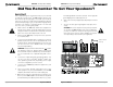
CE 4000 The amp with an Attitude! CE 4000 The amp with an Attitude! Did You Remember To Get Your Speakons®? Quick Start! You’ve waited a long time for this! We know you just can’t wait to crank up your new Crown® CE 4000 amplifier. And you sure don’t want to flip through pages of tech-talk just to find out where the on switch is. So that’s why we provided you with this quick and simple page to get you up and running right away.
CE 4000 The amp with an Attitude! CE 4000 The amp with an Attitude! Fig. 1.1 The CE 4000 Amplifier 1 Welcome Thanks for buying this CE 4000 amplifier. Here at Crown, we appreciate your support, and we think you’ll find that you’ve also done yourself a favor by choosing Crown. You see, CE 4000 amplifiers have been engineered from the bottom up for top-notch performance and unmatched reliability.
CE 4000 The amp with an Attitude! How to Use This Manual CE 4000 The amp with an Attitude! Features This manual will help you correctly install, set up and operate your CE 4000 amplifier, including mounting, mode selection, standard input and output wiring, advanced features and options setup, and typical operation. Please be sure to read all instructions, warnings and cautions.
CE 4000 The amp with an Attitude! CE 4000 The amp with an Attitude! Controls, Indicators & Connectors Fig. 1.2 The Big Picture: Controls, Indicators & Connectors* * Shown with standard input module and Neutrik Speakon® / 5-way binding post output connectors option.
CE 4000 The amp with an Attitude! 2 Installation Follow these instructions for a detailed explanation of CE 4000 installation procedures and options. If you just want to get up and running as quickly as possible, see the Quick Start section on page 6. 2.1—Begin with the amplifier turned off and disconnected from the power receptacle. The CE4000 power switch is located on the left side of the front panel; it is off (“O”) when depressed on the left.
CE 4000 The amp with an Attitude! Fig. 2.3 Typical Input Wiring CE 4000 The amp with an Attitude! Output Wiring Tips 1. This amp offers Neutrik Speakon® connectors to minimize wiring mistakes.* We also encourage you to choose carefully when selecting speaker enclosure connectors. 2. To prevent possible short circuits, wrap or otherwise insulate exposed loudspeaker cable connectors. 3.
CE 4000 The amp with an Attitude! 2.6—Check to make sure that adequate ventilation has been provided. Even though this amplifier has some of the most efficient heat sinks in the marketplace, it must be able to breathe. So make sure that the front vents are never blocked and that the exhaust fan (out the back) notblocked or covered by cables. An amplifier running at high sound pressure levels into low-impedance loads will typically put out lots of hot air, so make sure it can go somewhere.
CE 4000 The amp with an Attitude! CE 4000 The amp with an Attitude! Fig. 2.
CE 4000 The amp with an Attitude! CE 4000 The amp with an Attitude! Fig. 2.5 DJ Application Note: Mono hookup requires custom wiring on Neutrik connectors. See Figure 4.8 for more information.
CE 4000 The amp with an Attitude! CE 4000 The amp with an Attitude! 3 Operation Figure 3.1 Front Panel Indicators & Controls Your CE 4000 amp is really very easy to operate, once it has been properly configured. If your amplifier has not yet been set up or configured, please refer to the installation instructions found in Section 2 of this manual, or consult with your system installer. Follow these steps when first turning on your amplifier: 1 Turn down the level of your audio source.
CE 4000 The amp with an Attitude! CE 4000 The amp with an Attitude! Figure 3.2 Back Panel Controls 3. If the transformer thermal protection circuit is activated. 4. If amplifier output wires develop a short-circuit. 5. Should the amplifier output stage become non-operational. The fault status of the amplifier can also be monitored remotely by attaching a signalling device to the Fault jack located on the amplifier back-panel.
CE 4000 The amp with an Attitude! CE 4000 The amp with an Attitude! Mode Switch: This two-position switch, located on the back panel, allows the selection of either Stereo or Bridge-Mono mode of operation. 4 Crown Pro Information Guides Stereo mode provides identical power output to each of the two amplifier output channels. Bridge-Mono Mode combines the two amplifier output channels into a single mono channel with twice the voltage of a single stereo channel.
CE 4000 The amp with an Attitude! CE 4000 The amp with an Attitude! Fig. 4.3 Balanced Input Wiring Hum and Buzz Tips 1. It is imperative that all of your electrical equipment share the same power ground reference. 2. Unless you are interfacing to a microphone, the shield of the cable should only be connected at one end. (See Fig.4.3) 3. Do not pass signal ground between electrical components in a grounded source system. 4.
CE 4000 The amp with an Attitude! CE 4000 The amp with an Attitude! Fig. 4.4 Unbalanced Input Wiring Why Speakon? For amplifiers, the most popular termination device on professional products has been the dual banana (which incidentally was pioneered by Crown with the DC300 model).
CE 4000 The amp with an Attitude! CE 4000 The amp with an Attitude! To assemble the Neutrik Speakon NL4FC connector, complete the following steps: Fig.4.7 Stereo Output Wiring 1. Slide the bushing (E) and chuck (D) onto the end of the cable as shown in Figure 4.5.* Fig.4.5 Order of Assembly for theNeutrik® Speakon®NL4FC Connector 3b.
CE 4000 The amp with an Attitude! Fig.4.10 Connector Assembly: Chuck into Connector Housing 5 Advanced Features & Options BCA® 5. Slide the chuck (D) along the cable and insert into the housing, making sure that the large notch on the outer edge of the chuck lines up with the large groove on the inside of the connector housing. The chuck should slide easily into the insert/housing combination until only approximately 3/8-inch (9.
CE 4000 The amp with an Attitude! Typical non-switching power supplies require large, heavy transformers in order to produce the required power at the output stage. These transformers must be large to absorb the substantial waste that occurs when operating at 50 to 60 Hz (standard AC supplied by the power company). By contrast, switching power supplies can operate with a much smaller (and lighter) transformer because they first convert the AC up to a much higher frequency, thereby reducing waste.
CE 4000 The amp with an Attitude! CE 4000 The amp with an Attitude! Features of the SST-SX crossover include: • Neutrik® Combo ¼-inch (6.35-mm) and XLR input jacks. • Barrier block balanced outputs. • Mono-summed sub-bass output. • Optional high-pass filter bypass on amplified outputs adapts system for full-range use. • 24-dB/octave Linkwitz-Riley tuned filters. • Crossover switchable between 80 and 120 Hz. • Neutrik® Combo ¼-inch (6.35-mm) and XLR input jacks.
CE 4000 The amp with an Attitude! SST-SBSC (Summed Bass Stereo Crossover) Module Crown’s advanced SST-SBSC module offers ten user-specified crossover frequencies, CD horn EQ and summed subbass output for driving subs (see Figure 5.3 for block diagram). The SST-SBSC offers the following features: • Stereo biamp. • 12-, 18- and 24-dB (Linkwitz-Riley) / octave filters. • CD horn equalization. • Mono summing of sub-bass output for driving subs.
CE 4000 The amp with an Attitude! Fig. 5.4 Fault Status LED Circuitry CE 4000 The amp with an Attitude! (model CE4C) connectors installed in your amplifier in place of the standard Neutrik Speakon® plus 5-way binding post outputs (model CE4D) at time of ordering. See Figures 5.6 and 5.7. For information on adding optional output connector modules to an existing CE 4000 amplifier, please contact Crown Technical Support. Fig. 5.
CE 4000 The amp with an Attitude! Principles of Operation mance. Warning: Details of closed loop amplifier design are beyond the scope of this description and if discussed, would surely put most readers to sleep! Audio Signal Path For the sake of simplicity, only channel one of the audio signal path is described. Signal is presented to the CE 4000 through one of three connectors when using the standard input module. Each channel is outfitted with a balanced XLR / phone jack, and a barrier strip.
CE 4000 The amp with an Attitude! used for low to moderate duty work. If the amplifier is delivering large amounts of power into low impedance loads, the heatsinks or transformer may heat up enough to increase the speed of the fan to medium and possibly to high speed. If the temperature continues to increase, the TLC circuit uses the compressor to reduce the gain of the input stage and thus reduce the power dissipated by the amplifier.
CE 4000 The amp with an Attitude! Power LED is driven from the low-voltage supply. Power Supply Operation AC power enters the amplifier through a power cord equipped with an IEC (unplugable) connector. It then is passed through the EMI filter. Circuits that use switching technology will normally send a small amount of high-frequency noise back down the power cord and into the power distribution system. This noise must be removed in order to sell the unit in certain parts of the world.
CE 4000 The amp with an Attitude! 7 Specifications CE 4000 The amp with an Attitude! Damping Factor: Greater than 1000 from 10 Hz to 400 Hz.* Note: All measurements are in Stereo mode with 8-ohm loads and an input sensitivity of 26-dB gain at 1-kHz rated power unless otherwise specified. Power Crosstalk: Better than 50 dB below rated power, 20 Hz to 20 kHz. Common Mode Rejection (CMR): Better than 70 dB from 20 Hz to 1 kHz. Output Power: (see Figure 7.1). DC Output Offset (Shorted Input): ±10 mV.
CE 4000 The amp with an Attitude! Clip: A red LED for each channel which turns on when distortion becomes audible in the amplifier output. Fault: Normally off, this red indicator will blink under five different conditions: 1. When the amplifier is first powered up, until the unit is ready for operation. 2. If the heatsinks reach a temperature above normal working limits. 3. If the transformer thermal protection circuit is activated. 4. If amplifier output wires develop a short-circuit. 5.
CE 4000 The amp with an Attitude! Fig.7.1 CE4000 Output Power CE 4000 The amp with an Attitude! CE 4000 Power Chart 8 Service Maximum power @ 1 kHz with 0.5% THD Your amplifier should only be serviced by a fully trained technician at an authorized service center. 4 ohm Dual 1800W* 1200W 8 ohm Dual 600W 2 ohm Dual CAUTION: To prevent electric shock, do not remove covers. No user serviceable parts inside. Refer servicing to a qualified technician.
CE 4000 The amp with an Attitude! CE 4000 The amp with an Attitude! Send copies of the shipping receipts to Crown to receive reimbursement. Your repaired unit will be returned via UPS ground. Please contact us if other arrangements are required. Factory Service Shipping Instructions: Always use the original factory packing to transport the unit.
3 YEAR NORTH AMERICA WORLDWIDE SUMMARY OF WARRANTY The Crown Audio Division of Crown International, Inc., 1718 West Mishawaka Road, Elkhart, Indiana 46517-4095 U.S.A. warrants to you, the ORIGINAL PURCHASER and ANY SUBSEQUENT OWNER of each NEW Crown product, for a period of three (3) years from the date of purchase by the original purchaser (the “warranty period”) that the new Crown product is free of defects in materials and workmanship.
Crown Factory Service Information Shipping Address: Crown Audio, Inc., Factory Service, Plant 2 SW, 1718 W. Mishawaka Rd., Elkhart, IN U.S.A.