
Specifications


page 17
Studio Reference I & II Professional Studio Amplifiers
Operation Manual
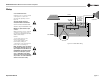
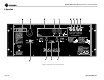
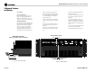
3.3 Back Panel Connectors and
Controls
I. Reset Switch
This back panel switch can be used to trip and
reset the AC mains circuit breaker (see Section
4.2.4).
J. Power Cord
For 120 VAC, 60 Hz North American units, the
Studio Reference I includes a 10 AWG power
cord and NEMA TT30P plug, and the Studio
Reference II includes a 12 AWG cord and
NEMA 5-15P plug. Other units are shipped
with an appropriate power cord and plug.
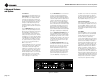
K. PIP Module
The standard P.I.P.-FX input module is provided
with your amplifier. It provides female XLR
input connectors. Each pair of XLR and phone
jack connectors is wired in parallel so the
unused connector can be used as a “daisy
chain” output to connect a source to multiple
amplifiers. Other PIP modules can be used in
place of the P.I.P. -FX to provide additional fea-
tures that customize your amplifier for different
applications (see Section 4.5).
L. Balanced XLR Inputs
A balanced three-pin female XLR connector is
provided on the P.I.P.-FX (K) for input to each
channel. Caution: Do not use the
Channel 2 input in either mono mode.
M. Output Connectors
Two pairs of versatile 5-way binding posts are
provided for the output of each channel so mul-
tiple loudspeakers can be connected easily.
They accept banana plugs, spade lugs or bare
wire.
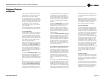
N. Stereo/Mono Switch
This switch is used to select one of three oper-
ating modes. Stereo mode is used for normal
two-channel operation, Bridge-Mono mode is
used to drive a single channel with a load
impedance of at least 4 ohms, and Parallel-
Mono mode is used to drive a single channel
with a load impedance of less than 4 ohms.
WARNING: Turn off the amplifier before
changing this switch (see Sections 2.5.1,
2.5.2 and 2.5.3).
O. Balanced Phone Jack Inputs
A balanced 1/4-inch phone jack is provided for
input to each channel. They may be used with
either balanced (tip, ring and sleeve) or unbal-
anced (tip and sleeve) input wiring (see Section
3.3). These inputs are in parallel with the PIP
connector, so they should not be used as inputs
if the installed PIP has active circuitry.
Caution: Do not use the channel 2 input
in either mono mode.
P. Ground Lift Switch
The input signal ground may be isolated from
the AC ground with this switch to help prevent
unwanted ground loops. It affects only the
phone jacks (O). It has no effect on the PIP
module’s XLR connectors. Activating the switch
inserts an impedance between the sleeve of
each phone input jack and the circuit ground.
See Section 4.4.3.
• Input Sensitivity Switch
The three-position input sensitivity switch
inside the amplifier can be accessed by remov-
ing the PIP module. Settings include 0.775
volts and 1.4 volts for rated output, and 26 dB
voltage gain (see Section 4.4.4).
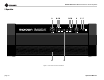
3 Operation