Xs Series Xs500 Xs700 Operation Manual Xs900 Xs1200 Obtaining Other Language Versions: To obtain information in another language about the use of this product, please contact your local Crown Distributor. If you need assistance locating your local distributor, please contact Crown at 574-294-8000. This manual does not include all of the details of design, production, or variations of the equipment. Nor does it cover every possible situation which may arise during installation, operation or maintenance.
Xs Series Power Amplifiers Important Safety Instructions 1) 2) 3) 4) 5) 6) 7) 8) 9) 10) 11) 12) 13) 14) page 2 Read these instructions. Keep these instructions. Heed all warnings. Follow all instructions. Do not use this apparatus near water. Clean only with a dry cloth. Do not block any ventilation openings. Install in accordance with the manufacturer’s instructions.
Xs Series Power Amplifiers DECLARATION of CONFORMITY Crown International, Inc. Issued By: FOR COMPLIANCE QUESTIONS ONLY: Crown International, Inc. 1718 W. Mishawaka Road Elkhart, Indiana 46517 U.S.A. Sue Whitfield 574-294-8289 swhitfield@crownintl.com European Representative's Name and Address: Nick Owen 35, Bassets Field Thornhill Cardiff.
Xs Series Power Amplifiers Table of Contents Important Safety Instructions ........................................................... 2 4 Advanced Features and Options ............................. 14 Declaration of Conformity ................................................................ 3 4.1 Protection Systems ...............................................................14 1 Welcome ....................................................... 5 4.1.1 Output Current Limiting ........................
Xs Series Power Amplifiers Xs500 2-ohm Dual (per ch.) 4-ohm Dual (per ch.) 8-ohm Dual (per ch.) 4-ohm Bridge 8-ohm Bridge 1 kHz Power* 750W** 500W 400W 1,600W** 1,450W *1 kHz Power: refers to maximum average power in watts at 1kHz with 0.15% THD. ** at 0.5% THD. Xs700 2-ohm Dual (per ch.) 4-ohm Dual (per ch.) 8-ohm Dual (per ch.) 4-ohm Bridge 8-ohm Bridge 1 kHz Power* 900W** 750W 450W 1,900W** 1,645W *1 kHz Power: refers to maximum average power in watts at 1kHz with 0.15% THD. ** at 0.5% THD.
Xs Series Power Amplifiers 2 Setup 2.1 Unpack Your Amplifier Please unpack and inspect your amplifier for any damage that may have occurred during transit. If damage is found, notify the transportation company immediately. Only you can initiate a claim for shipping damage. Crown will be happy to help as needed. Save the shipping carton as evidence of damage for the shipper’s inspection. We also recommend that you save all packing materials so you will have them if you ever need to transport the unit.
Xs Series Power Amplifiers 2 Setup 2.4 Choose Input Wire and Connectors Crown recommends using pre-built or professionally wired balanced line (two-conductor plus shield), 22-24 gauge cables and connectors. At the amplifier inputs, use either: • 3-pin male XLR cable ends, • TRS or TS 1/4" phone plugs, or • Phoenix-style connectors. Unbalanced lines may be used, but may result in noise over long cable runs. Figure 2.3 shows XLR wiring, Figure 2.4 shows 1/4" phone plug wiring, and Figure 2.
Xs Series Power Amplifiers 2 Setup 2.6 Wire Your System 2.6.1 Stereo Mode Typical input and output wiring is shown in Figures 2.8 and 2.9. INPUTS: Connect input wiring for both channels. OUTPUTS: Connect speakers to the 5-way binding posts or to the two Speakon® connectors. See the details below. Connection to 5-way binding posts: 1. Connect speaker 1 positive (+) lead to the amp’s Channel-1 positive (red) binding post. CHANNEL 2 2.
Xs Series Power Amplifiers 2 Setup 2.6.3 Bridge-Mono Mode Typical input and output wiring is shown in Figure 2.10. NOTE: Crown provides a reference of wiring pin assignments for commonly used connector types in the Crown Amplifier Application Guide available at www.crownaudio. OUTPUTS: Connect the speaker across the red binding posts of each channel. Do not use the black binding posts when the amp is being operated in Bridge-Mono mode. IMPORTANT: Set the Bridge/Normal switch to “Bridge.
Xs Series Power Amplifiers 2 Setup 2.7 Connect to AC Mains Connect your amplifier to the AC mains power source (power outlet) with the supplied AC power cordset. First, connect the IEC end of the cordset to the IEC connector on the amplifier; then, plug the other end of the cordset to the AC mains. The AC Mains indication light on the front panel should be lit. WARNING: The third prong of this connector (ground) is an important safety feature.
Xs Series Power Amplifiers 3 Operation 3.1 Precautions Your amplifier is protected from internal and external faults, but you should still take the following precautions for optimum performance and safety: 1. Before use, your amplifier first must be configured for proper operation, including input and output wiring hookup. Improper wiring can result in serious operating difficulties.
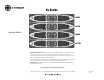
Xs Series Power Amplifiers 3 Operation 3.2 Front Panel Controls and Indicators E. AC Mains Indicator I. Temp Indicator A. Cooling Vents Red LED indicates that AC power is present at the power cord, even if the amplifier is not turned on. Red LED, one for each channel, indicates that channel(s) are in thermal protect mode. Front-to-rear forced airflow. F. Fault Indicator J. Power Switch B. Gain Controls Two or four grey rotary level controls, one for each channel.
Xs Series Power Amplifiers 3 Operation 3.3 Back Panel Controls and Connectors A. 4-Pole Speakon Output Connector One connector is used per channel. It accepts a 4-pole Speakon connector. See Figure 2.5 and Table 1 for connector wiring. B. Normal/Bridge Switch Two-position switch selects between normal (stereo) operation and Bridge-Mono operation. C. Circuit Breaker Provides overload protection. D. XLR-1/4" Combo Input Connectors F.
Xs Series Power Amplifiers 4 Advanced Features and Options NOTE: For detailed information about these Crown amplifier features, please consult the Crown Amplifier Application Guide, available on the Crown website at www.crownaudio.com. 4.1 Protection Systems Your Crown amplifier provides extensive protection and diagnostic capabilities, including output current limiting, microprocessor-controlled DC protection, circuit breaker, and special thermal protection for the unit’s transformers. 4.1.
Xs Series Power Amplifiers 5 Troubleshooting CONDITION: No sound. CONDITION: Normal operation. POSSIBLE REASONS: POSSIBLE REASON: • The amplifier has just turned on and is still in the 4-second turn-on delay. • The amplifier is in “fault” mode. A Fault status can be triggered when one of the amplifier’s protection circuits is activated. First disconnect your speakers from the affected channel (s) one by one to determine if one of the loads is shorted.
Xs Series Power Amplifiers 6 Specifications Minimum Guaranteed Power Xs500 Xs700 Xs900 Xs1200 Dual, 2 ohms (per ch.) 750W* 900W* 1200W* 1600W* Dual, 4 ohms (per ch.) 500W 750W 900W 1100W Dual, 8 ohms (per ch.) 400W 450W 600W 650W Bridge mono, 4 ohms 1600W* 1900W* 2500W* 3000W* Bridge mono, 8 ohms 1450W 1645W 2100W 2300W Performance Xs500 Xs700 Xs900 Xs1200 1.4V 1.4V 1.4V 1.
Xs Series Power Amplifiers 6 Specifications Performance Xs500 Xs700 Xs900 Xs1200 > 200 > 200 > 200 > 200 Crosstalk (below rated power) at 1 kHz at 20 kHz > 55 dB > 55 dB > 55 dB > 55 dB > 67 dB > 62 dB > 65 dB > 45 dB DC Output Offset (Shorted input) ± 75 mV ± 75 mV ± 75 mV ± 75 mV 20 kilohms, 10 kilohms 20 kilohms, 10 kilohms 20 kilohms, 10 kilohms 20 kilohms, 10 kilohms 2-8 ohms 4-8 ohms 2-8 ohms 4-8 ohms 2-8 ohms 4-8 ohms 2-8 ohms 4-8 ohms 32:1 (30.1 dB) 38:1 (31.
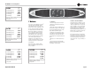
Xs Series Power Amplifiers 7 AC Power Draw and Thermal Dissipation This section provides detailed information about the amount of power and current drawn from the AC mains by Xs Series amplifiers and the amount of heat produced under various conditions. The calculations presented here are intended to provide a realistic and reliable depiction of the amplifiers. The following assumptions or approximations were made: • The amplifier’s available channels are loaded, and full power is being delivered.
Xs Series Power Amplifiers 7 AC Power Draw and Thermal Dissipation Figure 7.1 Xs500 Power Draw, Current Draw and Thermal Dissipation at Various Duty Cycles Figure 7.2 Xs700 Power Draw, Current Draw and Thermal Dissipation at Various Duty Cycles Figure 7.
Xs Series Power Amplifiers 7 AC Power Draw and Thermal Dissipation Figure 7.
Xs Series Power Amplifiers 8 Service Crown amplifiers are quality units that rarely require servicing. Before returning your unit for service, please contact Crown Technical Support to verify the need for servicing. This unit has very sophisticated circuitry which should only be serviced by a fully trained technician. This is one reason why each unit bears the following label: CAUTION: To prevent electric shock, do not remove covers. No user serviceable parts inside.
Xs Series Power Amplifiers 9 Warranty UNITED STATES & CANADA SUMMARY OF WARRANTY 3 AR YE Crown International, 1718 West Mishawaka Road, Elkhart, Indiana 46517-4095 U.S.A. warrants to you, the ORIGINAL PURCHASER and ANY SUBSEQUENT OWNER of each NEW Crown product, for a period of three (3) years from the date of purchase by the original purchaser (the “warranty period”) that the new Crown product is free of defects in materials and workmanship.
Xs Series Power Amplifiers 9 Warranty 3 AR YE WORLDWIDE EXCEPT USA & CANADA SUMMARY OF WARRANTY WHAT THE WARRANTOR WILL DO Crown International, 1718 West Mishawaka Road, Elkhart, Indiana 46517-4095 U.S.A.
Xs Series Power Amplifiers THIS PAGE INTENTIONALLY LEFT BLANK page 24 Operation Manual
Xs Series Power Amplifiers Crown Audio Factory Service Information Shipping Address: Crown Audio Factory Service, 1718 W. Mishawaka Rd., Elkhart, IN 46517 PLEASE PRINT CLEARLY SRA #: __________________(If sending product to Crown factory service.
Xs Series Power Amplifiers THIS PAGE INTENTIONALLY LEFT BLANK page 26 Operation Manual
Xs Series Power Amplifiers THIS PAGE INTENTIONALLY LEFT BLANK Operation Manual page 27