
Instruction manual


Operation Manual
Xs Series Power Amplifiers
page 12
A
B
C
ED
F
G
HI J
3 Operation
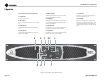
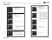
Figure 3.1 Front Panel Controls and Connectors
3.2 Front Panel Controls and Indicators
A. Cooling Vents
Front-to-rear forced airflow.
B. Gain Controls
Two or four grey rotary level controls, one for each chan-
nel.
C. Bridge Indicator
Yellow LED indicates that amplifier is in Bridge-Mono
mode.
D. Power Indicator
Yellow LED indicates that amplifier has been turned on
and AC power is available.
E. AC Mains Indicator
Red LED indicates that AC power is present at the power
cord, even if the amplifier is not turned on.
F. Fault Indicator
Red LED illuminates when amplifier is in protect mode.
Also illuminates briefly during normal power-up when
amplifier is first switched on.
G. Signal Indicators
Two green LEDs, one for each channel, illuminates when
the channel’s input signal level is above –40 dBu.
H. Clip Indicators
Two red LEDs, one for each channel, illuminates when the
channel’s output signal is being overdriven.
I. Temp Indicator
Red LED, one for each channel, indicates that chan-
nel(s) are in thermal protect mode.
J. Power Switch
Amplifier is on when the switch is depressed in the
right-hand position. When the power switch is off and
the unit is plugged into AC power, the amplifier is in
standby mode; the AC mains are still connected to the
unit.