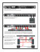
® ® PA Quick Start Guide Three-Way Setup An illustrated guide to setting up your DriveRack® PA using three amplifiers (high, mid, and low).
® ® ® Complete Equalization & Loudspeaker Control System PA Featuring Custom Tunings User Manual
IMPORTANT SAFETY INSTRUCTIONS WARNING FOR YOUR PROTECTION PLEASE READ THE FOLLOWING: CAUTION RISK OF ELECTRIC SHOCK DO NOT OPEN KEEP THESE INSTRUCTIONS A T T E N T I O N : RISQUE DE CHOC ELECTRIQUE - NE PAS OUVRIR W A R N I N G : TO REDUCE THE RISK OF FIRE OR ELECTRIC SHOCK DO NOT EXPOSE THIS EQUIPMENT TO RAIN OR MOISTURE The symbols shown above are internationally accepted symbols that warn of potential hazards with electrical products.
IMPORTANT SAFETY INSTRUCTIONS LITHIUM BATTERY WARNING CAUTION! This product may contain a lithium battery.There is danger of explosion if the battery is incorrectly replaced. Replace only with an Eveready CR 2032 or equivalent. Make sure the battery is installed with the correct polarity. Discard used batteries according to manufacturer’s instructions. ADVARSEL! Lithiumbatteri - Eksplosjonsfare.Ved utskifting benyttes kun batteri som anbefalt av apparatfabrikanten.
® DriveRack PA Table of Contents Introduction Section 5 - Application Guide 0.1 Defining the DriveRack® PA .........................ii 0.2 Service Contact Info........................................iii 0.3 Warranty...........................................................iv 5.1 5.2 5.3 5.4 2X6 Crossover.................................................30 2X5 Crossover.................................................31 2X4 Crossover.................................................32 2X3 Crossover....
® DriveRack PA INTRODUCTION INTRO CUSTOMER SERVICE INFO Defining the DriveRack WARRANTY INFO ®
® Introduction INTRODUCTION DriveRack PA Drive your PA to a whole new level of performance with the DriveRack® PA Complete Equalization & Loudspeaker Control System. The DriveRack PA from dbx Professional Products represents a complete integration of the key elements that help ensure optimal loudspeaker system management in PA-specific applications.
® DriveRack PA Introduction By including every form of processing necessary to drive the signal from the mixer to the power amp, the DriveRack® PA allows you to eliminate all other processing devices normally found in large and cumbersome traditional drive rack systems of the past. The DriveRack® PA Loud Speaker Management System includes two balanced XLR inputs, as well as six balanced XLR output connectors. 0.2 Service Contact Info If you require technical support, contact dbx Customer Service.
® Introduction DriveRack PA 0.3 Warranty This warranty is valid only for the original purchaser and only in the United States. 1. The warranty registration card that accompanies this product must be mailed within 30 days after purchase date to validate this warranty. Proof-of-purchase is considered to be the burden of the consumer. 2. dbx warrants this product, when bought and used solely within the U.S., to be free from defects in materials and workmanship under normal use and service. 3.
® DriveRack PA Section 1 Getting Started ®
® Section 1 Getting Started DriveRack PA 1.1 Rear Panel Connections Left/Mono Left/Mono IEC Power Cord Receptacle The DriveRack® PA comes with a power supply that will accept voltages ranging from 100V120V at frequencies from 50Hz-60Hz. An IEC cord is included. EU version accepts 220V-240V at frequencies from 50Hz-60Hz. Outputs 1-6 The output section of the DriveRack® PA offers six electronically balanced XLR connectors.
® DriveRack PA Getting Started Section 1 LCD Display The backlit LCD display of the DriveRack® PA provides the user with all of the vital processing information of the DriveRack® PA including: signal routing, effect block editing and Wizard Setup functions. The display will also notify the user if any internal clipping is taking place within the unit. The following message will appear: CLIP.
® Section 1 DriveRack PA Getting Started Signal Path Block Diagram The following diagram shows the logical and intuitive signal path of the input, effect modules, and output of the DriveRack® PA.
® DriveRack PA Getting Started Section 1 The RTA MIC input button is used to engage the RTA input connector. LCD DisplayAll operational information of the DriveRack® PA is displayed here. The display will also notify the user if any internal clipping is taking place within the unit. The following message will appear: CLIP. Data Wheel - The data wheel is used to scroll through the program menu of the DriveRack® PA.
U 1 St Tri-Amp Section 1 Rack PA WIZARD em Setup EQ WIZARD WIZARD Rack PA WIZARD em Setup EQ WIZARD WIZARD Setup Input as MONO REO. O Rack PA WIZARD em Setup EQ WIZARD WIZARD Q t mic to RTA Press RTA button. EQ Setup EQ as Dual Stereo no turn down the gain. Press when done. Warning T button pressed. eaker Main PA X X Passive umber of lters.
® DriveRack PA Section 1 • You will now rotate the wheel to match the same setting as your amplifier of choice. Note that based on your amp selection, the DriveRack® PA will initially display the recommended setting of that particular amp for obtaining maximum headroom. This is done to match unity gain from the DriveRack® PA and your amplifier. Note that if Sub Speakers are included in the speaker selection, you will be asked if the sub woofer is bridged or mono.
ri-Amp Section 1 ® DriveRack PA Getting Started Highand Amplifier High Amplifier AmpItLevel Amp the Bridging panel RTA XLR input, press the High button. is recommended that Low you use Select Sensitivity Select an amplifier Adjust level Select microphone. If you wish to bypass the previous optional dbx RTA-M Crwn MacroTech 1202 same as your amp same as your amp 0.
® DriveRack PA ack PA WIZARD m Setup EQ WIZARD IZARD U 1 ack PA WIZARD Tri-Amp m St Setup EQ WIZARD IZARD DriveRack PA WIZARD System Setup Auto EQ WIZARD AFS WIZARD AFS Please turn down the mixer gain. Press AFS Select Number of fixed filters. > 6 NEXT PG when done. F F F F F F L L L L L L AFS Select fixed type > Speech Q t mic to RTA Press RTA button.
Select Main PA JBL SRX >SR4702X Passive Dual o ning Select an amplifier >None >Crwn MacroTech 1202 DriveRack PA Getting LStarted Auto EQ : Pink Noise R Auto EQ : Pink Noise Mic Level Mic Level Turn Up Level Turn Up Level Pink Level > 18dB Pink Level > 18dB Auto EQ type has been selected, press the button and the display will read: AFS Select fixed type > Speech Slowly Increase the mixer gain to desired level.
® DriveRack PA Section 2 Editing Functions EDITING FUNCTIONS ®
Section 2 Editing Functions ® Editing Functions DriveRack PA The DriveRack® PA has been carefully designed and engineered to ensure that all aspects of operation are intuitive and logical. Simply stated, the DriveRack® PA operating system was designed with user’s best interest in mind. 2.1 Basic Navigation Modes Navigational aspects of the DriveRack® PA are clear, concise and more important: flexible.
® DriveRack PA Editing Functions Section 2 2.3 Navigatingthe the EQ Section (28-GEQ and PEQ) Navigating "EQ Section" To edit the parameters of the EQs used in a selected program, simply use the following procedure. From program mode, press the EQ button to reach the EQ module to be edited. Successive presses of the EQ button will move through each channel. Navigate through the Pages of the selected EQ section by depressing "Next Page" or "Prev Page" successively until arriving at the desired Page.
Successive presses of the Data wheel will select effect parameters within the currently selected page. ® Section 2 DriveRack PA Editing Functions 2.5 Navigating the XOVER Section Navigating the Delay Section To edit theFrom parameters the Crossover in button. a selected program, use thewill following procedure. From program mode, programofmode, press theused Delay Pressing thesimply Data Wheel select the effect parameter to be edited. press the X-OVER button.
® DriveRack PA Editing Functions Section 2 2.7 Navigating the Comp/Limiter Section Navigating the Compressor/Limiter Section From program mode, press the comp/limiter button to move to eithter the Compressor or Limiter module. Once you have reached the Crossover module, successive presses of COMP/LIMITER button will move through each channel that utilizes either a Compressor (pre Crossover) or Limiter (post-crossover) module.
The NEXT and PREV buttons scroll through the pages of selected module. Section 2 Successive presses of the Data wheel will select effect parameters within the currently selected page. ® DriveRack PA Editing Functions Navigating the Utility Section 2.9 Navigating the Utility Section Navigating the Utility Section From program mode, press the UTILITY button. Pressing the Data Wheel will select the effect parameter to be edited. UTILITY UTILITY From program mode, UTILITY button.
® DriveRack PA Section 3 SOFTWARE OPERATING FUNCTIONS ®
Section 3 ® DriveRack PA Operating Functions The Operation section of the DriveRack® PA will be your key to successful navigation of the operation of the DriveRack® PA. The following information provides descriptions about program functions and operating functions of the DriveRack® PA. 3.1 Program Definition The first step in understanding the thorough programming capabilities of the DriveRack® is to understand the elements involved, that when combined, define a complete “program.
® DriveRack PA 3.3 Editing Factory Programs Once you have reached the module that you wish to edit, simply use the and buttons to move through the pages within the module. The wheel is used to edit parameter values.
Section 3 ® Operating Functions • Rotating the wheel will change the icons on the currently selected position. • Pressing the wheel will toggle between upper and lowercase letters, numbers or symbols. • Use the and button to move icon positions.
® DriveRack PA Section 4 PARAMETERS DETAILED PARAMETERS ®
® Section 4 DriveRack PA Detailed Parameters The DriveRack® PA offers complete editing flexibility, by offering in-depth control over every parameter within each effect module. The following section will provide you with descriptions and explanations of all parameters within the DriveRack® PA. 4.1 Pre-Crossover The DriveRack® PA’s Pre-Crossover EQ section may be configured as a single or linkable 28 band graphic EQ. EQ On/Off Turns the GEQ on and off.
® DriveRack PA Detailed Parameters Section 4 Clear Live/All This parameter clears the filters. If Clear Live is selected, then (if invoked) the live filters are reset. If Clear All is selected, then (if invoked) all of the filters are reset. When either Clear Live or Clear All is selected, the third parameter row displays “Start w/ Data Wheel.” If Clear (none) is selected, then nothing is displayed on this row.
Section 4 ® Detailed Parameters DriveRack PA 4.3 Subharmonic Synthesizer The Subharmonic Synthesizer module has been specifically optimized to enhance Bass audio material for use in a variety of professional applications, including nightclub and dance DJ mixing, theatre and film sound, music recording, live music performance and broadcasting.
® DriveRack PA Detailed Parameters Section 4 4.5 Post-CROSSOVER PEQ In addition to the pre-crossover EQ options within the signal path, the DriveRack® PA also offers a 2 or 3-band parametric EQ after the crossover section. The parameters for the post-crossover EQ are as follows and are user adjustable. PEQ On/Off Turns the PEQ band on and off. The following figure shows the constant Q parametric filter. Flatten/Restore This parameter either flattens the PEQ or restores the PEQ to its original shape.
Section 4 ® Detailed Parameters DriveRack PA 4.6 Compressor/Limiter The DriveRack® PA also offers Compression and Limiter modules. The Compressor is a full bandwidth Stereo Compressor located prior to the Crossover. The Compressor is the perfect tool for tightening uneven signal sources such as vocals and guitars. The Limiters are located on each stereo output channel and have been strategically placed for speaker and amplifier protection.
® DriveRack PA Detailed Parameters Section 4 LIMITER Limiter On/Off Turns the Limiter module on and off. OverEasy (O) Off to 10 There are ten levels of OverEasy® that can be used for the limiters. The point when the compressor starts to compress is the "knee." When the compressor starts to reduce the level of a signal abruptly as it passes over the threshold this is called "hard knee" compression. OverEasy® (soft knee as it is sometimes called) is when the volume of the sound is compressed gradually.
Section 4 ® Detailed Parameters DriveRack PA USER NOTES ® ® ® 28 DriveRack® PA User Manual
® DriveRack PA Section 5 APPLICATION GUIDE ®
® Section 5 DriveRack PA Application Guide This Application guide section is provided to offer suggested installation applications of the DriveRack® PA that will allow you to optimize peak performance of the units. Note that the 25 included application programs represent the extensive flexibility of the DriveRack® units. These applications can be used verbatim, or as sample reference guide templates for designing countless audio applications. 5.1 2X6 Crossover Hardware 1.
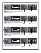
® DriveRack PA Section 5 Application Guide 5.2- 2X5 Crossover Hardware 1. Connect the outputs from the mixer to the inputs of the DriveRack®. 2. Connect the outputs of the DriveRack® PA and run to the selected speaker amplifier. 3. Make sure that the mixer and power amps are turned off prior to powering up the DriveRack® PA. Software 1. From Program mode, select factory program #F2 (3 Way w/mSub) as a template, or use the Wizard to setup the specific program. 2.
Section 5 ® DriveRack PA Application Guide 5.3 2X4 Crossover Hardware 1. Connect the outputs from the mixer to the inputs of the DriveRack®. 2. Connect the outputs of the DriveRack® PA and run to the selected speaker amplifier. 3. Make sure that the mixer and power amps are turned off prior to powering up the DriveRack® PA. Software 1. From Program mode, select factory program #F14 (MP212 2X4) as a template, or use the Wizard to setup the specific program. 2.
® DriveRack PA Application Guide Section 5 5.4 - 2X3 Crossover Hardware 1. Connect the outputs from the mixer to the inputs of the DriveRack®. 2. Connect the outputs of the DriveRack® PA and run to the selected speaker amplifier. 3. Make sure that the mixer and power amps are turned off prior to powering up the DriveRack® PA. Software 1. Use the Wizard to setup the specific program. 2. Once the program has been chosen, press the DATA wheel to load the program.
Section 5 ® Application Guide DriveRack PA USER NOTES ® ® ® 34 DriveRack® PA User Manual
® DriveRack PA Appendix ®
Appendix A ® DriveRack PA A.1 Factory Reset In the event that a reset is required, the DriveRack® PA offers you the option of performing a “Soft” or “Hard” reset. The Soft Reset resets all operating parameters except user programs. The Hard Reset Procedure will reset all programmable information back to the factory defaults. All Power-Up Functions require a button(s) to be pressed and held as the unit power is turned on. DriveRack PA Power-Up Button Functions Factory (“Hard”) Reset.
® DriveRack PA Appendix A A.3 Specifications Analog Inputs: Number of Inputs: Connectors: Type: Impedance: Max input line level: CMRR: RTA Mic Phantom Voltage: RTA Mic EIN: (2) Line inputs.
® DriveRack PA Appendix A out positive affect. You may be able to see if a lifted band is a mode by manually adjusting a lifted EQ band - if no change in the EQ is perceived, you probably are seeing a mode in your frequency response. To reduce the effect of this mode, try different microphone positions and adjust the location of your speakers, then repink the room for a more effectual Graphic EQ adjustment.
® DriveRack PA Appendix A Right Low Left Low Right Mid Left Mid Right High Meters Outputs Left High A.
® DriveRack PA Appendix A A.
® DriveRack PA Appendix A A.8 System Setup and Gain Structure The DriveRack PA offers a wide range of tools for sound system design and setup. These tools can make your system more efficient and better sounding, but to get the best possible sound it is important to use these tools properly. In the DriveRack PA we have included a Wizard setup tool to help in system setup. If you use the Wizard to set up your DriveRack PA it will automatically set the limiters for some amplifier selections.
Appendix A ™ DriveRack Once you have found the clip point of your amplifiers, you can mark this position and turn the amplifiers back up to the point where they are clipping. You can now use the output limiters in the DriveRack PA to protect the amplifier from clipping no matter what you do at the console. With the amplifiers clipping, now go to the Limiter page of the DriveRack PA and turn the limiter for each output band on. Make sure that the threshold is all the way up to +20dB.
™ DriveRack Appendix A USER NOTES ® ® ® ® ® ® 43
® 8760 South Sandy Parkway • Sandy, Utah 84070 Phone: (801) 568-7660 • Fax (801) 568-7662 Int’l Fax: (801) 568-7583 E-mail us at: customer@dbxpro.com or visit us on the web at: www.dbxpro.
dbx DriveRack PA Interactive Training Guide Proceed 1
Main Menu Overview Basic Navigation Virtual DriveRack PA Go To Index 2
Index Overview The DriveRack PA provides: •Input Graphic EQ •Advanced Feedback Suppression •Subharmonic Synthesis •Input Compression •Crossover (Up to 3-Way) •Output Parametric EQ •Output Limiters •Output Driver Alignment Delays (up to 10 ms) Back To Main Menu Proceed 3
Index Overview This illustration shows the DriveRack PA installed in a typical 3 Way system.
Index Overview This illustration shows what the DriveRack PA actually replaces in a sound system.
Index Overview The processsing in the DriveRack PA is stereo tied. The input GEQ (Graphic EQ) is the only exception. It can be configured in “Dual Mono” mode if desired.
Index Basic Navigation Don’t be afraid to experiment with the buttons and controls on the DriveRack PA. It is recommended that you familiarize yourself with these controls before connecting the device to your system. Once you feel comfortable with the navigation of the unit you can easily perform the Factory Hard Reset procedure (as described in the back of the Owner’s Manual). This Hard Reset will set the device back to it’s factory default state.
Index Basic Navigation This is the LCD display.
Index Basic Navigation This is the Button Array. Use these buttons to navigate through the DriveRack PA.
Index Basic Navigation Pressing any of these buttons will take you to the corresponding function. Note: Some buttons will toggle through the various input and output processing modules associated with that button. For example; the EQ button will toggle through the input GEQ and output PEQ modules when pressed multiple times.
Index Basic Navigation Pressing the PREV PG (Previous Page) & NEXT PG (Next Page) buttons allow you to navigate through the various pages within a module.
Index Basic Navigation The DATA ENCODER is your “SELECT” button when pressed in.
Index Basic Navigation Pressing the DATA ENCODER in will move the cursor on the currently selected page.
Basic Navigation Index Turning the DATA ENCODER will change the selected parameter.
Index Virtual DriveRack PA Left Click on an item to learn more.
Index RTA Input Jack This is the RTA INPUT jack. Connect the dbxRTA-M microphone to this connector using a standard XLR microphone cable. This connection supplies 15 Volts of phantom power to the microphone.
Index RTA Input Button This is the RTA INPUT button. Pressing this button will engage the Auto EQ.
Index LCD/Button Array This is the LCD DISPLAY. This display allows you to view the various pages within the DriveRack PA. This is the BUTTON ARRAY. Use these buttons to navigate through the DriveRack PA Left Click on a BUTTON or TEXT in the LCD to learn more.
Preset # Index This shows the currently selected PROGRAM or PRESET #. Note: There are USER and FACTORY presets. 1-25 are USER presets & can be overwritten. Presets 26-50 are identical to 1-25 (from the factory), but are FACTORY presets & cannot be overwritten.
Index Preset Name This is the NAME of the currently selected preset. Note: If this area reads “Not Loaded”, you must press the SELECT button (DATA ENCODER) in to load the selected preset.
Index Input Configuration These letters indicate how the inputs are configured. The “L” stands for LEFT & the “R” stands for RIGHT. Note: If there is an “M” here then the input is configured as “MONO”. This means that a mono input was selected instead of stereo inputs in the System Setup Wizard.
GEQ/PEQ Index These are the EQ modules. The “G” is the input GRAPHIC EQ & the “P” stands for the output PARAMETRIC EQs. This is the EQ button. Press this button to enter the Graphic or Parametric EQ modules. Note: Pressing this button multiple times will toggle through the input GEQ & output PEQ modules.
GEQ (Graphic EQ) Index This is the input GEQ. It is used to help compensate for the coloration of the room and provides a more tonally balanced sounding system within a venue.
GEQ (Graphic EQ) Index This is the first page in the GEQ (Graphic EQ) module. The GEQ is the only processor within the DriveRack PA that can be unlinked. This displays which INPUT you have selected. LR=Left & Right. Here you can turn the GEQ ON & OFF. This GRAPH shows the GEQ curve when the EQ is set. Here you can FLATTEN and RESTORE the GEQs settings.
GEQ (Graphic EQ) Index This is the second page in the GEQ (Graphic EQ) module. This displays which INPUT you have selected. LR=Left & Right. This GRAPH shows the GEQ curve when the EQ is set. Here you can select the “FREQUENCY CENTER” or BAND that you would like to edit. Here you can adjust the GAIN (boost or cut) of the selected frequency or band.
Index PEQ (Parametric EQ) These are the output PEQ modules. They are generally used to help flatten the response of the loudspeaker drivers.
Index PEQ (Parametric EQ) This is the first page in the PEQ (Parametric EQ) module. This displays which OUTPUT you have selected. This GRAPH shows the PEQ curve when the EQ is set. Here you can turn the PEQ ON & OFF. Here you can FLATTEN and RESTORE the GEQs settings. Here you can select which types of filters will be available (LOW SHELF, HIGH SHELF, BOTH or all BELL).
Index PEQ (Parametric EQ) This is the second page in the PEQ (Parametric EQ) module. This displays which OUTPUT you have selected. This GRAPH shows the PEQ curve when the EQ is set. This displays which BAND is selected. This is “FREQUENCY 1”. Here you can change the GAIN (boost or cut) of band 1. Here you can adjust the “SLOPE” or “Q” of the filter depending upon what you selected on the first page.
Index PEQ (Parametric EQ) This is the third page in the PEQ (Parametric EQ) module. This displays which OUTPUT you have selected. This GRAPH shows the PEQ curve when the EQ is set. This displays which BAND is selected. This is “FREQUENCY 2”. Here you can change the GAIN (boost or cut) of band 2. Here you can adjust the “Q” of the filter.
Index PEQ (Parametric EQ) This is the fourth page in the PEQ (Parametric EQ) module. This displays which OUTPUT you have selected. This GRAPH shows the PEQ curve when the EQ is set. This displays which BAND is selected. This is “FREQUENCY 3”. Here you can change the GAIN (boost or cut) of band 3. Back To EQ Here you can adjust the “SLOPE” or “Q” of the filter depending upon what you selected on the first page. “S”= Slope “Q”=Width Note: You will only see this page when editing the “High Outputs”.
Index Feedback (AFS) This is the FEEDBACK or AFS module. Back To Buttons This is the FEEDBACK button. Press this button to enter the AFS (Advanced Feedback Suppression) module.
Feedback (AFS) Index This is the input AFS module. It is used to help control feedback in the system.
Feedback (AFS) Index This is the first page in the FEEDBACK or AFS module. Here you can CLEAR all filters or just the Live filters. Here you can turn the AFS ON & OFF. This shows you how many FIXED VS LIVE filters are allocated. It also shows you how many filters are set.
Index Feedback (AFS) This is the second page in the FEEDBACK or AFS module. Here you can select whether AFS is in LIVE or FIXED mode. Here you can select how wide or narrow the notch filters will be. Speech=Wide Music High=Narrow This shows you how many FIXED VS LIVE filters are allocated. It also shows you how many filters are set. Here you can select how many filters are ALLOCATED as Fixed.
Feedback (AFS) Index This is the third page in the FEEDBACK or AFS module. Here you can turn the Live Filter Lift ON & OFF. Here you can set HOW LONG the Live Filters will remain set before they are lifted. This shows you how many FIXED VS LIVE filters are allocated. It also shows you how many filters are set.
Index Subharmonic Synth This is the SUBHARMONIC SYNTH module. Back To Buttons This is the SUBHARMONIC SYNTH button. Press this button to enter the Subharmonic Synth module.
Index Subharmonic Synth This is the input Subharmonic Synth module. It is used to add extremely low frequencies to material that otherwise lacks these frequencies.
Index Subharmonic Synth This is the first page in the SUBHARMONIC SYNTH module. Here you can turn the Subharmonic Synth ON & OFF. Here you can set the MASTER LEVEL of the Subharmonic Synth process.
Index Subharmonic Synth This is the second page in the SUBHARMONIC SYNTH module. Here you can set the LEVEL of the first range of frequencies. Here you can set the LEVEL of the second range of frequencies.
Index Compressor/Limiter These are the Dynamics (COMPRESSOR & LIMITER) modules. This is the COMP/LIMITER button. Press this button to enter the input COMPRESSOR or output LIMITER modules. Note: Pressing this button multiple times will toggle through the input Compressor & output Limiter modules.
Index Compressor This is the input Compressor module. It is used to lower the dynamic range of the system. In other words, it brings louder signals down and softer signals up.
Compressor Index This is the first page in the input COMPRESSOR module. This is your THRESHOLD INDICATOR. “-”=Below Threshold “O”=In the Overeasy Range “+”=Over the Threshold This illustrates that you are editing the input “Left & Right” “Compressor” module. This is your GAIN REDUCTION METER. It shows how many dB of compression is taking place. Here you can turn the Compressor ON & OFF. Here you can turn OVEREASY mode ON & OFF. This is a variable knee (VariKnee) ranging from 1-10.
Compressor Index This is the second page in the COMPRESSOR module. This is your THRESHOLD INDICATOR. “-”=Below Threshold “O”=In the Overeasy Range “+”=Over the Threshold This illustrates that you are editing the input “Left & Right” “Compressor” module. Here you can set the RATIO. The RATIO determines how much compression will take place once the Threshold is exceeded. This is your GAIN REDUCTION METER. It shows how many dB of compression is taking place.
Index Limiter These are the output Limiter modules. They set a “ceiling” on the output level and help protect speakers from being overdriven and amplifiers from clipping.
Limiter Index This is the first (or high output) LIMITER module. This is your THRESHOLD INDICATOR. “-”=Below Threshold “O”=In the Overeasy Range “+”=Over the Threshold This shows which OUTPUTS you are editing. H=”Highs” Here you can turn the Limiter ON & OFF. This is your GAIN REDUCTION METER. It shows how many dB of limiting is taking place. Here you can turn OVEREASY mode ON & OFF. This is a variable knee (VariKnee) ranging from 1-10.
Limiter Index This is the second (or mid output) LIMITER module. This page will only be shown in a 3 Way system. This is your THRESHOLD INDICATOR. “-”=Below Threshold “O”=In the Overeasy Range “+”=Over the Threshold This shows which OUTPUTS you are editing. M=”Mids” Here you can turn the Limiter ON & OFF. This is your GAIN REDUCTION METER. It shows how many dB of limiting is taking place. Here you can turn OVEREASY mode ON & OFF. This is a variable knee (VariKnee) ranging from 1-10.
Limiter Index This is the third (or low output) LIMITER module. This page will only be shown in a 2 Way or 3 Way system. This is your THRESHOLD INDICATOR. “-”=Below Threshold “O”=In the Overeasy Range “+”=Over the Threshold This shows which OUTPUTS you are editing. L=”Lows” Here you can turn the Limiter ON & OFF. Back To Comp/Lim This is your GAIN REDUCTION METER. It shows how many dB of limiting is taking place. Here you can turn OVEREASY mode ON & OFF.
Index Xover (Crossover) This is the XOVER (Crossover) module. Back To Buttons This is the XOVER button. Press this button to enter the Crossover module.
Index Xover (Crossover) This is the Xover module. It is used to send the proper range of frequencies to each loudspeaker driver.
Xover (Crossover) Index This is the first page in the XOVER module. This page is for editing the HIGH PASS filter on the “Low Outputs”. The low outputs will only be available in a 2Way or 3-Way configuration. This shows which OUTPUTS you are editing. L=”Lows” This is the crossover point which is edited on this page. This is the crossover FREQUENCY for the high pass on the low outputs. This GRAPH shows you how the crossover points are set a at a glance. This is the OUTPUT GAIN for the low outputs.
Xover (Crossover) Index This is the second page in the XOVER module. This page is for editing the LOW PASS filter on the “Low Outputs”. The low outputs will only be available in a 2Way or 3-Way configuration. This shows which OUTPUTS you are editing. L=”Lows” This is the crossover point which is edited on this page. This is the crossover FREQUENCY for the low pass on the low outputs. This GRAPH shows you how the crossover points are set a at a glance.
Xover (Crossover) Index This is the third page in the XOVER module. This page is for editing the HIGH PASS filter on the “Mid Outputs”. The mid outputs will only be available in a 3Way configuration. This shows which OUTPUTS you are editing. M=”Mids” This is the crossover point which is edited on this page. This is the crossover FREQUENCY for the high pass on the mid outputs. This GRAPH shows you how the crossover points are set a at a glance. This is the OUTPUT GAIN for the mid outputs.
Xover (Crossover) Index This is the fourth page in the XOVER module. This page is for editing the LOW PASS filter on the “Mid Outputs”. The mid outputs will only be available in a 3Way configuration. This shows which OUTPUTS you are editing. M=”Mids” This is the crossover point which is edited on this page. This is the crossover FREQUENCY for the low pass on the mid outputs. This GRAPH shows you how the crossover points are set a at a glance.
Xover (Crossover) Index This is the fifth page in the XOVER module. This page is for editing the HIGH PASS filter on the “High Outputs”. This shows which OUTPUTS you are editing. H=”Highs” This is the crossover point which is edited on this page. This is the crossover FREQUENCY for the high pass on the high outputs. Back To X-Over This GRAPH shows you how the crossover points are set a at a glance. This is the OUTPUT GAIN for the high outputs.
Active Outputs Index These letters indicate which OUTPUTS are active and how they are configured. LH=Left High RH=Right High LM=Left Mid RM=Right Mid LL=Left Low RL=Right Low Note: You may see an “ML” rather than an “LL & “RL” for the subwoofer outputs. This means that a mono subwoofer was selected rather than stereo subs in the System Setup Wizard.
Previous Page Index This is the PREV PG (Previous Page) button. Press this button to go back to the previous page within the currently selected Last or module.
Index Next Page This is the NEXT PG (Next Page) button. Press this button to go to the next page within the currently selected Last or module.
Delay Index This is the DELAY button. Press this button to enter the Delay module. Note: Pressing this button multiple times will toggle through the Delay modules for the various active outputs.
Delay Index These are the output Delay modules. They are used to time align the drivers. These delays are suitable for driver alignment but not delay towers (10 ms max).
Delay Index This is the first (or high output) DELAY module. This shows which OUTPUTS you are editing. Here you can turn the delay module ON & OFF. H=”Highs” Here you can change the delay TIME in coarse or fine increments. Up to 10 ms is available. Here you select whether you want to set the time in MILLISECONDS, FEET, or METERS.
Delay Index This is the second (or mid output) DELAY module. This page will only be available in a 3 Way setup. This shows which OUTPUTS you are editing. Here you can turn the delay module ON & OFF. M=”Mids” Here you can change the delay TIME in coarse or fine increments. Up to 10 ms is available. Here you select whether you want to set the time in MILLISECONDS, FEET, or METERS.
Delay Index This is the third (or low output) DELAY module. This page will only be available in a 2 Way or 3 Way setup. This shows which OUTPUTS you are editing. Here you can turn the delay module ON & OFF. L=”Lows” Here you can change the delay TIME in coarse or fine increments. Up to 10 ms is available. Back To Delay Here you select whether you want to set the time in MILLISECONDS, FEET, or METERS.
Index Program This is the PROGRAM button. Think of this button as an “Exit” button. It will take you back to the main program screen, backing you out of any page that you are currently viewing or editing. Note: The only Last that will render this button inactive is the Auto EQ. You must first depress the RTA Input button before you can exit the Auto EQ.
Utility Index This is the UTILITY button. Press this button to enter the Utility Last. WARNING! Do not press and hold the UTILITY button. doing so will take you to a debug/calibration Last. Changing these parameters will result in miscalibration of the DriveRack PA. This would require the device to be re-calibrated at the main factory. If you accidentally enter this Last, keep pressing the NEXT PG button until the display reads “Loading...”.
Utility Index This is the UTILITY page. Here you can adjust the CONTRAST of the LCD display. Here you can select whether the GEQ (Graphic EQ) or RTA (Real Time Analyzer) is shown when running the Auto EQ. Here you can turn the SALES BANNER On & Off.
Store Index This is the STORE button. Press this button to store your preset. Note: You must press this button a total of three times to actually store the preset. •1st Press-Here you can name the preset. •2nd Press-Here you can select which user location to store the preset to. •3rd Press-This actually stores the preset.
Store Index The first press of the Store button allows you to NAME the preset. Name the PRESET. •Press the SELECT button (DATA ENCODER) in to toggle between the characters which include upper case letters, lower case letters, numerals, & blank space (or punctuation & symbols). •Turn the DATA ENCODER to scroll through the characters. • Use the NEXT PG & PREV PG buttons to highlight another character to edit.
Store Index This is the second page in the Store menu. Here you can select the LOCATION to store the preset to. In other words, which USER PRESET you would like to overwrite. Select the LOCATION to store the preset to. Just turn the DATA ENCODER to select the location.
Store Index The third press of the STORE button actually stores your preset with the name that you selected & at the location which you selected. The preset location that you stored to will automatically be loaded. The preset (or program) is being STORED to memory.
Wizard Index This is the WIZARD button. Press this button to enter the Wizard.
Wizard Index This is the WIZARD menu. Here you can enter the SYSTEM SETUP WIZARD (step 1), AUTO EQ WIZARD (step 2), or AFS WIZARD (step 3). Select the SYSTEM SETUP WIZARD. Select the AUTO EQ WIZARD. Select the AFS WIZARD. Just turn the DATA ENCODER to make the selection. Then press the NEXT PG button to proceed.
Index Data Encoder This is the DATA ENCODER. Turning it will change the currently selected parameter. It is also the SELECT button when pressed in. Pressing it in will move the arrow (cursor) in the display. In other words it allows you to “Select” the parameter that you would like to edit within the currently selected page then turn the DATA ENCODER to change that parameter.
Input Meters Index These are the INPUT METERS measured using the dBu scale. These meters show the level of the audio that is driving the input stage of the DriveRack PA. Note: The +20 (red) LEDs at the top of the LED meters are your clip indicators.
Index Limiter Threshold LEDs These are the OUTPUT LIMITER THRESHOLD indicators. They give you a visual indication when the output limiters are engaged. Note: These LEDs do not indicate clipping. The +20 (red) LEDs at the top of the meters are the clip indicators.
Output Meters Index These are the OUTPUT METERS measured using the dBu scale. These meters show the level of the audio that is driving the output stage of the DriveRack PA. Note: The two far left meters correlate to the “Low” outputs, the two in the middle are for the “Mid” outputs & the two on the right are for the “High” outputs. The +20 (red) LEDs at the top of the meters are your clip indicators.
Power Switch Index This is the POWER SWITCH. This turns the DriveRack PA on & off. Note: Always remember to turn your amps on last and off first.
Index Power Receptacle This is the POWER RECEPTACLE. Plug the AC cable in here. Note: Make sure the text below the receptacle matches the voltage in your Country. If it does not, do not plug the unit in. There are two different Voltage models. The US/JA model operates at 100-120 Volts. The EU/UK model operates at 220-240 Volts. If you suspect that you may have the wrong model, please contact the dealer that you purchased the unit from or dbx Technical Support.
Index Low Output Jacks These are the LOW OUTPUT jacks. Connect these jacks to the subwoofers amplifier or low frequency drivers. These are the only outputs that can be mono summed within the DriveRack PA. Note: When a “Mono” subwoofer is selected in the System Setup Wizard, a mono summed signal will be fed to both the LEFT and RIGHT LOW OUTPUTS. It is also possible to send a full range signal out of these outputs if needed. Please see the “Advanced Configurations” section for more information.
Mid Output Jacks Index These are the MID OUTPUT jacks. Connect these jacks to the mid frequency drivers amplifier when using a 3-Way system. Note: It is possible to make these jacks output a full range signal.
Index High Output Jacks These are the HIGH OUTPUT jacks. Connect these jacks to the high frequency drivers amplifier in a 2-Way or 3-Way system or the amplifier for a pair of full range speakers in a passive or powered full range system.
Index Operating Level Switch This is the NOMINAL OPERATING LEVEL switch. This should be set to match the operating level of the device that is plugged into the DriveRack’s inputs (this is typically a mixer). Note: The selections for the nominal operating level are +4 dBu and -10 dBV. If you are unsure what the operating level of your mixer is, please contact the mixer manufacturer. Also, see the gain structure section in the “Setup” section of this guide.
Input Jacks Index These are the INPUT jacks. They have a selectable nominal operating level of +4 dBu or -10 dBV. Connect these jacks to the device pre DriveRack (typically a mixer).
Pin 1 Lift Switch Index This is the PIN 1 LIFT switch. If you are having problems with ground loops (i.e. hum), try pressing this switch in. This will break the connection between the ground pin in the cable and the input jacks.
Index •AFS •AFS Wizard •Auto EQ Wizard •Auto EQ Plot •Block Diagram •Button Array •Comp/Limiter Button •Compressor •Crossover •Cursor •Data Encoder •Delay •Delay Button •EQ Button •Feedback Button •GEQ •High Output Jacks •Input Configuration •Input Jacks •Input Meters •LCD Contrast •LCD Display •Limiter •Limiter Threshold LEDs •Low Output Jacks •Mid Output Jacks •Navigation •Next Page Button •Operating Level Switch •Output Meters •Overview •PEQ •Pin 1 Lift Switch •Power Receptacle •Power Switch •Preset Na