
User manual

Getting Started
®
®
®
®
®
®
DriveRack
®
PA User Manual
4
Section 1
DriveRack
®
PA
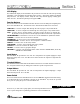
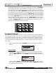
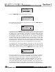
Signal Path Block Diagram
The following diagram shows the logical and intuitive signal path of the input, effect mod-
ules, and output of the DriveRack
®
PA.
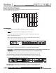
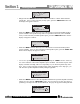
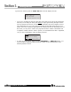
Connections
• When setting up the DriveRack
®
PA, make connections as follows:
• Always make connections prior to applying power to the unit.
• Connect the output from the sending device (mixer) to either of the two XLR
inputs connectors shown below.
• Make output connections from any one of the six output XLR connectors shown
below to the input of the selected power amps.
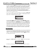
• If you will be “pinking” the room through the use of the RTA, connect the selected
R
T
A micr
ophone to the fr
ont-panel XLR input, and press the RTA input button.
•
IMPORTANT- It is imperative that the power amps are turned off prior to cycling power to the Driverack
®
PA.
Always make sure that your power amps are the last item turned on and the first turned off.
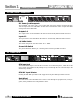
Once all of the connections have been made and the unit is powered up, you can
navigate through the entire signal path of the DriveRack PA from the front panel of
the unit. The display pr
ovides you with a clear and concise overview of each aspect
of the signal path from the input to the output section.
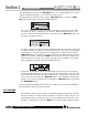
The features of the front panel of the DriveRack
®
PA are as follows from left to right.
RTA MIC Input- This XLR input is used for the connection of a RTA microphone.
CROSSOVER/ALIGNMENT DELAY/GRAPHIC EQ/PARAMETRIC EQ/AUTO/EQ
Left/MonoLeft/Mono
GEQ
GEQ
Meters
Left Input
Right Input
Left High
Right High
Left Mid
Right Mid
Left Low
Right Low
M
ic Input
Outputs
Stereo Compressor
AFS Notch Filters
SubHarmonic Synth
3-Band PEQ 2-Band PEQ 2-Band PEQ
Peak Stop Limiter Peak Stop Limiter Peak Stop Limiter
Alignment Delay Alignment Delay Alignment Delay
Crossover Section - (2X3, 4,5,6)
Stereo/Mono
Pink Noise
Micr Pre amp
RTA
Meters