Cruise TV DBS-30500 Mobile Mobile Satellite Television System User’s Guide All rights reserved, patent pending Copyright 1999 by Cruise TV A subsidiary of Audiovox Specialized Applications, LLC M-01345
M-01345 NOTICE!! Important Warranty Information Keep this User Guide with the Antenna System at all times. Place label here For Customer Service, contact your Authorized Cruise TV Dealer or call Cruise TV Technical Support at 1-877-845-8750.
M-01345 Page 1 TABLE OF CONTENTS 1. WELCOME..................................................................................................................... 3 1.1 2. 3. 4. 5. Features of your DBS-30500...............................................................................3 SYSTEM OVERVIEW .................................................................................................... 2 2.1 Antenna-Pedestal Assembly....................................................................
M-01345 Page 2 TABLE OF CONTENTS (CONTINUED) 6. TROUBLESHOOTING ................................................................................................. 17 7. GLOSSARY ................................................................................................................. 18 8. PRECAUTIONS ........................................................................................................... 19 9. WARRANTY........................................................................
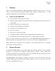
M-01345 Page 3 1. Welcome Thank you for purchasing Cruise TV’s DBS-30500 Mobile Satellite Television System. You now own one of the most advanced automatic satellite systems available, providing access to over 200 channels of digital television and CD quality audio programming. 1.
M-01345 Page 4 The Cruise TV DBS-30500 was designed and has been manufactured from the same technology as found in satellite-tracking systems for military and commercial customers worldwide, since 1969. This experience has created this revolutionary new satellite television receiving system. The DBS-30500 has three main parts, the Antenna-Pedestal Assembly, the Antenna Control Unit (ACU) and the Satellite Receiver.
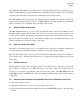
M-01345 Page 5 2.5 Optional EchoStar Upgrade To use the DBS-30500 with an EchoStar Receiver you must order EchoStar Upgrade Kit, P/N 130742-102. *NOTE: Satellite receiver not included in upgrade kit.
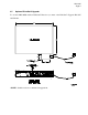
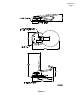
M-01345 Page 6 DBS-30500 Antenna Audio/ DBS-30500 RF Cable Video Satellite Receiver Cable TV Coax Cable Communications Cable Controller Cable DBS-30500 Antenna Control Unit (ACU) 12V DC Power Supply Figure 1. Diagram of DBS-30500 Antenna System Connections 3. Specifications 3.1 Mechanical Reflector Diameter ....................................................................................... 18” Roof Hole Size (cable) .....................................................................
M-01345 Page 7 Figure 2
M-01345 Page 8 4. System Operation This section describes the operation of the DBS-30500 satellite system. It does not focus on the operation of the receiver, except where it pertains directly to the operation of the DBS-30500 satellite system. For questions about your satellite receiver, please refer to the receiver’s operating instructions. 4.1 Choosing a Location It is important that your vehicle have an unobstructed view of the southern sky.
M-01345 Page 9 4.2 Indicators and Controls Cruise TV Figure 4. Antenna Control Unit (ACU) Front Panel Figure 5.
M-01345 Page 10 4.3 Turning on the System Before powering on the system check to see that all of the cables on the rear of the antenna control unit (ACU) are engaged and secure. To apply power to the system, toggle the power switch to the ON position. The Status light will begin to blink slowly (approximately once per second). This indicates the system has power applied and is in idle mode. To turn off power, return the power switch to the OFF position. The ACU status light will turn off. 4.
M-01345 Page 11 4.6 Automatic Elevation Determination An alternative to entering the elevation angle is to set the front panel elevation switches to “00”. This enables a search mode that sweeps the entire sky to find the satellite. While this is the simplest acquisition method, several additional minutes may be required to find the satellite. When in the “00” automatic mode the system will search the entire viewable sky until the signal is found. 4.
M-01345 Page 12 Figure 6. DBS-30500 Deployed Cruise TV Figure 7. DBS-30500 Stowed 4.8 Automatic Receiver On/Off The DBS-30500 Antenna Control Unit will automatically switch your satellite receiver on when the antenna is deployed and switch it off when your antenna is fully stowed. You just choose the channel you want to watch! 4.
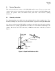
M-01345 Page 13 is called the signal’s “peak.” The process of locating the exact azimuth and elevation angle at which the maximum signal strength can be found is called “peaking.” It is similar to looking at a lighted lamp through a straw. The lamp represents the satellite and the straw is your satellite dish. As the straw points closer to the lamp, more light is visible through the straw.
M-01345 Page 14 eventually locate and peak on the DBS signal. Altogether, the DBS-30500 will make eight complete passes spanning twelve degrees searching for the satellite’s signal when in the set elevation mode. When in the “00” automatic mode the system will search the entire sky until the signal is found. The azimuth (horizontal) movement of the antenna may not be perfectly smooth and may pause briefly from time to time during acquisition. This is normal while locating the satellite signal.
M-01345 Page 15 Table 1. Status Light Indications Blink Rate (per second) Description Steady off 0 Power switch is off or ACU is not plugged in. Flashing slowly and evenly 1 Power switch is on. System is stowed and idle. Flashing slowly, on long/off short 1 Satellite signal has been acquired. System is in peaking/tracking mode. Flashing medium and evenly 5 Antenna is moving to or from stow or is trying to acquire the satellite signal. Flashing quickly and evenly 10 Error condition detected.
M-01345 Page 16 5.1 Locating the Satellite in Semi-Automatic Mode Turn on your receiver and locate the satellite setup menu screen. Refer to your receiver manual to learn where this menu is located. Once the setup menu is displayed on your video monitor, set the zip code to your current location. The receiver will then display the elevation setting necessary to locate the satellite.
M-01345 Page 17 6. Troubleshooting Error conditions are indicated by a fast flashing Status light on the ACU’s front panel. Table 2 describes these error conditions and possible solutions for each. Table 2. Errors and Possible Solutions Symptom Cause Possible Solution Status light flashing fast and the receiver is off or is not displaying a message. The antenna is not moving. The satellite receiver is not responding correctly, if at all, to the ACU’s command and status requests.
M-01345 Page 18 7. Glossary The following is a glossary of terms used both within this User Guide and when talking about digital satellite television systems and DIRECTV. Azimuth – refers to the azimuth axis, indicating the rotating movement of the antenna about an axis perpendicular to the surface. Looking down on the antenna from above, the azimuth movement is either clockwise or counterclockwise.
M-01345 Page 19 8. Precautions ♦ To avoid injury, keep away from the dish when it is in motion and while it is plugged into the ACU. ♦ Do not open or remove any part of the ACU or the antenna. There are no user serviceable parts inside. ♦ Do not attempt to move the antenna by hand. Contact your Authorized Cruise TV Dealer or contact Cruise TV directly by calling 1-877-845-8750.
M-01345 Page 20 9. Warranty Cruise TV LLC warrants this product to be free from defects in material and workmanship for two (2) years’ parts and one (1) year labor. Proof of purchase in the form of a bill of sale or invoice indicating the product installation date must be presented to obtain warranty service.
M-01345 Page 21 10. Cruise TV Satellite System Receiver Compatibility Matrix B ra n d R e c e iv e r S O N Y S A T -B 1 S A T -B 2 S A T -B 3 S A T -A 1 S A T -A 2 S A T -A 3 S A T -A 4 S A T -A 5 0 V 7 .4 S A T B 5 0 V 7 .5 S A T -A 5 0 V 7 .6 8 S A T B 5 0 V 7 .6 8 S A T -A 5 5 V 8 .
M-01345 Page 22 Cruise TV Satellite System Receiver Compatibility Matrix (cont’d) Cruise TV Satellite System Receiver Compatibility Matrix Brand Receiver SONY SAT-B1 SAT-B2 SAT-B3 SAT-A1 SAT-A2 SAT-A3 SAT-A4 SAT-A50 V7.4 SAT B50 V7.5 SAT-A50 V7.68 SAT B50 V7.68 SAT-A55 V8.
M-01345 Page 23 EchoStar Dish Network (119 Degrees West) 11.
DIRECTV (101 Degrees West) M-01345 Page 24