English Version on Page 15.
Sicherheitshinweise BITTE BEACHTEN SIE DIE FOLGENDEN HINWEISE VOR INBETRIEBNAHME! DAS VON IHNEN ERWORBENE GERÄT IST NUR FÜR DEN BETRIEB AN EINEM 12-V-BORDNETZ EINES FAHRZEUGS AUSGELEGT. Andernfalls besteht Feuergefahr, die Gefahr eines elektrischen Schlages oder anderer Verletzungen. BITTE KEINE BEDIENUNG DES SOUNDSYSTEMS AUSFÜHREN, WELCHE VOM SICHEREN LENKEN DES FAHRZEUGS ABLENKEN KÖNNTE. Führen Sie keine Bedienungen aus, die Ihre Aufmerksamkeit längere Zeit in Anspruch nehmen.
Installationshinweise Achten Sie bei der Installation darauf, dass keine serienmäßig im Kfz vorhandenen Teile wie z.B. Kabel, Bordcomputer, Sicherheitsgurte, Tank oder ähnliche Teile beschädigt bzw. entfernt werden. Vergewissern Sie sich, dass der Verstärker am Montageort genügend Kühlung erhält. Montieren Sie das Gerät nicht in zu kleine, abgeschlossene Gehäuse ohne Luftzirkulation, in die Nähe von wärmeabstrahlende Teilen oder elektronische Steuerungen des Fahrzeuges.
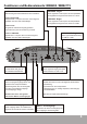
Funktionen und Bedienelemente: MXB280 / MXB2175 FILTER - Schalter HIGHPASS - Regler Position HIGH PASS: Hochpass-Filter - Frequenz wird nach unten begrenzt, einstellbar über den HIGH PASS-Regler. LOWPASS - Regler Dieser regelt die Trennfrequenz des Hochpassfilters. Der Regelbereich liegt zwischen 60Hz und 1.2kHz. Selektiert die gewünschte Betriebsart des Verstärkers. Dieser regelt die Trennfrequenz des Tiefpassfilters. Der Regelbereich liegt zwischen 40Hz und 150Hz.
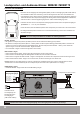
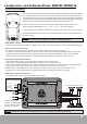
Lautsprecher- und Audioanschlüsse: MXB280 / MXB2175 2-Kanal Stereo-Modus • Verbinden Sie die Ausgänge des Steuergerätes (Radio) mit den Cincheingängen (LINE LEVEL INPUT) des Verstärkers mittels einer Cinchleitung. Falls Ihr Steuergerät nicht über einen Vorverstärker bzw. Cinchausgänge verfügt, können Sie den Verstärker über den Hochpegel-Eingang (HI INPUT) ansteuern.
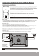
Lautsprecher- und Audioanschlüsse: MXB280 / MXB2175 Subwoofer-Modus mono gebrückt • Verbinden Sie die Ausgänge des Steuergerätes (Radio) mit den Cincheingängen (LINE LEVEL INPUT) des Verstärkers mittels einer Cinchleitung. Falls Ihr Steuergerät nicht über einen Vorverstärker bzw. Cinchausgänge verfügt, können Sie den Verstärker über den Hochpegel-Eingang (HI INPUT) ansteuern.
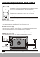
Funktionen und Bedienelemente: MXB480 / MXB4125 HI INPUT - Hochpegel-Eingänge Kanal 1/2 & 3/4 Diese Hochpegel-Eingänge dienen zum Anschluss der Lautsprecherkabel des Steuergeräts, falls Ihr Steuergerät nicht über Vorverstärker-Ausgänge (Cinchausgänge) verfügt. BASS BOOST - Regler Kanal 1/2 & 3/4 Dieser regelt die Bassanhebung von 0dB bis +12dB pro Kanalpaar. Benutzen Sie diese nicht gemeinsam mit den INPUT Cincheingängen.
Lautsprecher- und Audioanschlüsse: MXB480 / MXB4125 4-Kanal Stereo-Modus • Verbinden Sie die Ausgänge des Steuergerätes (Radio) mit den Cincheingängen (LINE LEVEL INPUT) des Verstärkers mittels einer Cinchleitung. Falls Ihr Steuergerät nicht über einen Vorverstärker bzw. Cinchausgänge verfügt, können Sie den Verstärker über den Hochpegel-Eingang (HI INPUT) ansteuern.
Lautsprecher- und Audioanschlüsse: MXB480 / MXB4125 2 x Subwoofer-Modus mono gebrückt • Verbinden Sie die Ausgänge des Steuergerätes (Radio) mit den Cincheingängen (LINE LEVEL INPUT) des Verstärkers mittels einer Cinchleitung. Falls Ihr Steuergerät nicht über einen Vorverstärker bzw. Cinchausgänge verfügt, können Sie den Verstärker über den Hochpegel-Eingang (HI INPUT) ansteuern.
Lautsprecher- und Audioanschlüsse: MXB480 / MXB4125 3-Kanal Stereo/Subwoofer-Modus • Verbinden Sie die Ausgänge des Steuergerätes (Radio) mit den Cincheingängen (LINE LEVEL INPUT) des Verstärkers mittels einer Cinchleitung. Falls Ihr Steuergerät nicht über einen Vorverstärker bzw. Cinchausgänge verfügt, können Sie den Verstärker über den Hochpegel-Eingang (HI INPUT) ansteuern.
Lautsprecher- und Audioanschlüsse: MXB480 / MXB4125 3-Kanal Stereo/Subwoofer-Modus Anschlussbelegung Hochpegel-Eingänge Subwoofer 4 - 8 Ohm Weiss: Linker LS Grün: Linker LS + Schwarz: Masse Braun: Rechter LS + Grau: Rechter LS - Verbinden Sie die Cinchleitungen vom Steuergerät mit Cincheingängen (INPUT CH1/CH2 & CH3/CH4).
Technische Daten MODELLE Kanäle Ausgangsleistung bei 14.4 Volt Watt an 4 Ohm - RMS / MAX. W Watt an 2 Ohm - RMS / MAX. W Ausgangsleistung bei 14.4 Volt gebrückt Watt an 4 Ohm - RMS W Watt an 4 Ohm - MAX.
Fehlerbehebung Fehler: keine Funktion 1. Die Verbindungskabel sind nicht korrekt angeschlossen. 2. Die Kabel haben keinen elektrischen und mechanischen Kontakt. 3. Sicherungen defekt. Im Falle des Austauschs achten Sie bitte auf den korrekten Wert der Sicherungen. Fehler: kein Ton aus Lautsprecher 1. Die Lautsprecherkabel oder Cinchkabel sind nicht korrekt angeschlossen oder defekt. 2. Die Lautsprecher sind defekt. Fehler: Ein bzw. zwei Kanäle ohne Funktion 1. Der Balance- bzw.
English Version Content Page 15 Safety Instructions General Installation Notes 16 MXB280 / MXB2175 Functions and Controllers 2-Channel Stereo-Mode: Speaker- and Audio-Connections Subwoofer-Mode mono bridged: Speaker- and Audio-Connections 17 17 18 19 MXB480 / MXB4125 Functions and Controllers 4-Channel Stereo-Mode: Speaker- and Audio-Connections 2 x Subwoofer-Mode mono bridged: Speaker- and Audio-Connections 3-Channel Stereo-/Subwoofer-Mode: Speaker- and Audio-Connections 20 21 22 23 24 Trouble Sho
Safety Instructions PLEASE ATTEND THE FOLLOWING ADVICES BEFORE THE FIRST OPERATION! THE PURCHASED DEVICE IS ONLY SUITABLE FOR AN OPERATION WITH A 12V ON-BOARD ELECTRICAL SYSTEM OF A VEHICLE. Otherwise fire hazard, risk of injury and electric shock consists. PLEASE DO NOT MAKE ANY OPERATION OF THE SOUNDSYSTEM, WHICH DISTRACT YOU FROM A SAFE DRIVING. Do not make any procedures, which demand a longer attention. Perform these operations not until you have stopped the vehicle on a safe place.
General Installation Notes The amplifier is generally mounted in the rear trunk area but can be mounted in any convenient area such as beneath a seat. Please be sure to locate this unit where you have reasonable air circulation and protection from moisture. When considering the mounting location you should minimize the length of the power and speaker leads. Minimizing both leads will yield a more reliable installation.
Functions and Controllers: MXB280 / MXB2175 FILTER - selector HIGH PASS - controller Position HIGH PASS: Highpass-Filter - The frequency will be limited to below, adjustable by the HIGH PASS controller. LOW PASS - controller Adjusts the cut-off frequency of the highpass filter. The range is adjustable from 60Hz to 1.2 kHz. Selects the desired operation mode of the amplifier. Adjusts the cut-off frequency of the lowpass filter. The range is adjustable from 40Hz to 150Hz.
Speaker- and Audio-Connections: MXB280 / MXB2175 2-Channel Stereo-Mode • Connect the RCA INPUTS of the amplifier to the head unit line outputs with appropriate RCA cables. If your head unit is not equipped with pre-amplifier RCA line outputs you can use the optional HI INPUTS (Highlevel Inputs). Connect therefore the speaker outputs of your head unit with the enclosed cable plug. Check the Wiring Diagram below.
Speaker- and Audio-Connections: MXB280 / MXB2175 Subwoofer-Mode mono bridged • Connect the RCA INPUTS of the amplifier to the head unit line outputs with appropriate RCA cables. If your head unit is not equipped with pre-amplifier RCA line outputs you can use the optional HI INPUTS (Highlevel Inputs). Connect therefore the speaker outputs of your head unit with the enclosed cable plug. Check the Wiring Diagram below.
Functions and Controllers: MXB480 / MXB4125 HI INPUT - inputs for channel 1/2 & 3/4 The High level Inputs are suitable for connecting the loudspeaker wires of the head unit, if the head unit is not equipped with pre-amplifier RCA line outputs. BASS BOOST - controller Adjust the bass boost from 0dB up to 12dB per channel pair. Never use the HI INPUTS and the RCA Inputs at the same time.
Speaker- and Audio-Connections: MXB480 / MXB4125 4-Channel Stereo-Mode • Connect the RCA INPUTS of the amplifier to the head unit line outputs with appropriate RCA cables. If your head unit is not equipped with pre-amplifier RCA line outputs you can use the optional HI INPUTS (Highlevel Inputs). Connect therefore the speaker outputs of your head unit with the enclosed cable plug. Check the Wiring Diagram below.
Speaker- and Audio-Connections: MXB480 / MXB4125 2 x Subwoofer-Mode mono bridged • Connect the RCA INPUTS of the amplifier to the head unit line outputs with appropriate RCA cables. If your head unit is not equipped with pre-amplifier RCA line outputs you can use the optional HI INPUTS (Highlevel Inputs). Connect therefore the speaker outputs of your head unit with the enclosed cable plug. Check the Wiring Diagram below.
Speaker- and Audio-Connections: MXB480 / MXB4125 3-Channel Stereo-/Subwoofer-Mode • Connect the RCA INPUTS of the amplifier to the head unit line outputs with appropriate RCA cables. If your head unit is not equipped with pre-amplifier RCA line outputs you can use the optional HI INPUTS (Highlevel Inputs). Connect therefore the speaker outputs of your head unit with the enclosed cable plug. Check the Wiring Diagram below.
Speaker- and Audio-Connections: MXB480 / MXB4125 3-Channel Stereo-/Subwoofer-Mode Wiring Diagram Highlevel Inputs Subwoofer 4 - 8 Ohms White: Left Speaker Green: Left Speaker + Black: Ground Brown: Right Speaker + Gray: Right Speaker - Connect the RCA cables from the head-unit with the RCA inputs (INPUT CH1/2 & CH3/4). Front Speakers 2 - 8 Ohms REFERENCE NOTE: Never use the HI INPUTS and the RCA Inputs at the same time.
Specifications MODELS MXB280 MkII Channels 2 Output Power Ratings at 14.4 Volts Watts at 4 Ohms - RMS / MAX. W Watts at 2 Ohms - RMS / MAX. W Watts at 4 Ohms - RMS W Watts at 4 Ohms - MAX. W Damping Factor 2 MXB480 MkII 4 4 2 x 110 / 220 2 x 175 / 350 4 x 100 / 200 4 x 125 / 250 1 x 200 1 x 350 2 x 200 2 x 250 1 x 400 > 150 1 x 700 > 150 4 x 60 / 120 MXB4125 MkII 2 x 60 / 120 2 x 100 / 200 Output Power Ratings at 14.
Trouble Shooting System does not turn on 1. Check all fuses. 2. Check all connections. 3. Measure the +12 volt and remote turn on voltages at the amplifier terminals. If these are non existent or low, take voltage measurements at fuse holders, distribution blocks, the head unit’s +12 volt and remote leads to localize the problem. Noise problems 1. Check the speaker wiring. 2. Speakers are damaged. No Signal at Channels 1. Set Balance and Fader from head unit on Zero-Position. 2.
Distribution: Audio Design GmbH Am Breilingsweg 3 76709 Kronau / Germany Tel. 07253/9465-0 · Fax 07253/9465-10 www.audiodesign.