
Datasheet
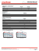
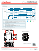

WIRING AND BLOCK DIAGRAM
INPUT
STATUS
+A3 13 +A1
-A4 14 -A2
L1 L2 L3
T1 T2 T3
XXXX
IND. CONT. EQ.
DRH3P60xxx
L1
L2
L3
L1
L2
L3
CONTROL
INPUT
/ > / > / >
Power Supply
90-265 VAC/VDC (for A Control Voltage)
8-32 VDC (for D Control Voltage)
Alarm Output (0.5 A/200 VDC, 120 VAC) Normally Open
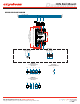
T1 T2 T3
General Use /
AC-51 Application
T1 T2 T3
T1 T2 T3
M
3
Motor Controller /
AC-53a Application
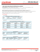
DRHP60x18
(3 controlled legs model)
Main Circuit
L1
T1
L2
T2
L3
T3
+A1
-A2
+A3
-A4
DRHP60x20
(2 controlled legs model)
Main Circuit
L1
T1
L2
T2
L3
T3
+A1
-A2
+A3
-A4
Alarm Output
(DRHP60x18 & DRHP60x20)
13
14
48-600 VAC, 50-60Hz
Do not forget to visit us at: www.crydom.com
Copyright © 2016 Crydom Inc. Specifications subject to change without notice.
Datasheet
DIN Rail Mount