
Datasheet
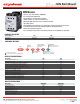
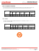

STATUS CHART
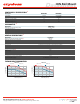
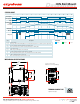
MECHANICAL SPECIFICATIONS
Tolerances: ±0.02 in / 0.5 mm
All dimensions are in: inches [millimeters]
Top/Bottom view (Fig. 1)
Fig. 1
TERMINAL SCREW TYPE
INPUT
STATUS
XXXX
IND. CONT. EQ.
DRH3
1.23
[31.3]
2.29
[58.3]
2.58
[65.5]
1.68
[42.7]
3.41
[86.7]
1.78
[45.3]
3.76
[95.6]
3.51
[89
]
2.91
[73.9]
0.23
[5.8]
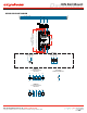
+A1
-A2
13+A3
14-A4
Blue
LED Color
Green Red
1, 15
2, 14
3
4, 12
5, 11
6, 10
7
8
9
13
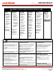
Initial Condition
Stand by condition. LED is blinking Blue. Fan is activated at full speed for 2 seconds after power is applied to A3
A1 is On, Output is activated, temperature rises. LED is Green
Fan is activated at 50% speed. If A1 is disabled, LED changes to blinking Blue
Fan is at 75% speed
LED changes to blinking Red, fan is at full speed
Output is Off, Alarm Output is On, LED changes to solid Red
If A1 is disabled while alarm output is active, LED alternates between Blue and Red
LED is solid Red, temperature starts to fall
Fan is activated at 50% speed, temperature is steady
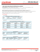
DescriptionStep
Fan Speed
LED Color
Alarm Output
Over Temperature
Output
Power Supply A3
Control Input A1
Alarm
Pre-alarm
1 2 3 4 5 6 7 8 9 10 11 12 13 14 15
3s 3s2s 50% 50%75% 75%100% 100%0%3s
Do not forget to visit us at: www.crydom.com
Copyright © 2016 Crydom Inc. Specifications subject to change without notice.
Datasheet
DIN Rail Mount