
Use and Care Manual


A. Choose the valve location.
Choose a location for the valve that is easily accessible. It is best to connect into the side of •
a vertical water pipe. When it is necessary to connect into a horizontal water pipe, make the
connection to the top or side, rather than at the bottom, to avoid drawing off any sediment from
the water pipe.
Disconnect the cold water supply line. Attach and tighten the saddle valve connector assembly, •
beingcarefulnottopinchorcrimpanytubingorwatersupplylinewhiletightening.UseTeon
®
tapetoensureatightt(Fig2).
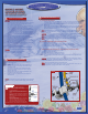
NOTE:
The saddle valve (Fig 2) clamps onto soft or hard tubing or pipe. It will make its own hole in
copper tubing but not in iron or brass. For brass or galvanized iron pipe, drill a ¼” hole in pipe before
mounting saddle valve.
CAUTION:
There is risk of electric shock. If possible, use a hand or cordless drill when drilling into
the water pipe. Be sure that drill, cord, and outlet are all properly grounded.
NOTE:
Do not turn handle before installing or while installing saddle valve. To prevent damage to
piercing needle, make sure that piercing lance does not project beyond the rubber gasket.
NOTE:
Leavehandleinthisposition(valveclosed)untillterinstallationiscomplete.
B. Assemble saddle-tapping valve assembly on tube.
Hold back plate against tube.1.
Hold saddle valve against tubing in a position directly opposite back plate.2.
Tighten screw so saddle valve and back plate are held securely against tube.3.
Tightenscrewrmly.Donotcrushtube.4.
C.Connectsourcewaterfeedtubingtovalvebodyusingcompressiontting.
Slide nut and sleeve onto tubing (in that order).1.
Install insert into plastic tubing.2.
Install tube with insert and sleeve into valve body.3.
Thread compression nut onto valve body. Tighten.4.
Turnsaddle-tappingvalvehandleclockwiseuntilitisrmlyseatedandpiercinglanceisfully5.
extended.
CAUTION:
Supply line is pierced and valve is closed. Do not open valve until system is activated.
Turn on cold water supply. Check saddle-tapping valve installation for leaks. Allow water to run from
faucet for a few minutes to clear any debris in the line caused by installation.
NOTE:
Ifowfromsinkfaucetisreduced,cleanfaucetaerator.
NOTE:
Connect the water supply line tubing to the system access board labeled “water inlet.” The
system is shipped with a red cap; remove it before inserting the tube.
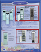
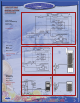
INSTALL WATER
COOLER SYSTEM
TO WATER SUPPLY
INSTALL WATER
COOLER SYSTEM
TO WATER SUPPLY
CAUTION:
Adjust the cold water supply line at the T-Valve (Fig 1) by
slowlyturningthehandletoreduceowtothesystem.
Connect the water supply line tubing to the system access board •
labeled “water inlet”. The system is shipped with a red cap;
remove it before inserting the tube.
Turn on the cold water supply line again. Make sure there is no •
leak at the connections. Recheck for water leaks.
Plug the power cord into a receptacle outlet. Make sure the •
system is plugged into a 110 volt grounded outlet which contains
a fuse or circuit breaker of 20 amps.
Turn the shut-off valve handle to the “ON” position to allow the •
coldwatertoowthroughthesystem.Checkthatwaterows
throughthecoldfaucet;waterwillnotowifelectricalisnot
plugged in.
Allowthewatertoowthroughthesystem.Checkall •
connectionsincludingtheltersandallothertubingandtting
connections inside the system for possible leaks.
Dispense the hot and cold water faucet/spouts and run water •
untilwaterowsfreelyandthereisnoairinthelines.Becareful:
water from hot faucet can scald your hands.
Allowwatertoowthroughthesystemtorellthecoldandhot•
tanks.
Flushlters/membrane.*•
Turn on the hot and cold tank switches. •
Donotusetherstthreereservoirsofwater.Theseushthe•
system.
CAUTION:
Flood stopper valve must be installed on the water cooler if
the water cooler is installed in a high rise building.
Recheck the system for water leaks.•
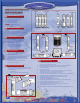
System Set-up & Preparation
6
The following procedures will prepare the system to deliver the
best possible drinking water.
Esurethatltersareinstalled,hotandcoldswitchesareoff,1.
the system is plugged in, and the top of the cabinet and the
reservoir lids are off.
Allowwaterowtollthereservoiranddrainthesystem2.
three times. Avoid water spills, and use a pan to catch the
waterfrombothdrains.*
Rellthereservoirandcovercabinetbyreplacinglids.Turn3.
both switches on after tanks are full.
Dispense two glasses of water from each faucet/spout to 4.
clear trapped air.
Filters/ROFlushingProcedures*
7
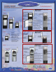
Installing the Saddle Valve
8
T-Valve Installation
WARNING
: Water supply pressure must not exceed 60 psi.
NOTE:T-Valveisdesignedforinstallationonexlinetubing.
NOTE: Always check the local plumbing codes before tapping into a water
line.
Turn off cold water supply.1.
Assemble T-Valve by screwing and tightening the shut-off 2.
valve into the water supply connector. Use thread tape on
threads.
Disconnect source water feed tubing from cold water supply.3.
Install T-Valve assembly in line with water feed tubing and 4.
water supply.
Remove nut from feed end of shut-off valve and slide over 5.
ltersupplytubing.
Press end of tubing over exposed nipple on shut-off valve. 6.
Ensureitiscompletelyseated.
Slide nut down tubing and tighten securely to shut-off valve.7.
Slowly turn on cold water supply and check for leaks.8.
OpenT-Valveshut-offvalveslowlytosupplywatertolter.9.
For further instructions on T-Valve assembly, see T-Valve product label.
Fig 1
Fig 2
*NOTE:
This drained water should be immediately disposed of properly
(
poured down a drain
) to prevent accidental spilling, as this water will
stain.
7