
Owner's manual
Dierential Pressure Test Set User Instructions
Overview
Using Crystal Engineering’s Dierential Test Set based XP2i-
DD and XP2i gauges, it’s possible to perform pressure dier-
ential measurements. By simply connecting your upstream
(+) and downstream (–) pressure lines to the 1/8” FNPT ttings
you are ready to go. This test set is capable of displaying
live or average dierential pressures (average of 10 samples)
depending upon which display mode you select.
Operation
A typical dierential pressure measurement may be done in
the following manner.
1 Select Units: Select your required unit of pressure mea-
surement on each gauge by pressing the
units
button
on each gauge independently. You may select dierent
units for each gauge but they must be set individually. The
dierential pressure will be displayed on the lower line of
the right (–) dual display gauge and will be in the same
units as the static pressure.
2 Select Display Options: Select the appropriate display
option on each unit using the
peak
button:
a Right hand (–) or dierential pressure gauge: Using
the
peak
button, select live pressure display (both
HI
and
LO
icons), or Average pressure over 10 read-
ings (both
HI
,
LO
, and
AVG
icons). Static pressure will
be display on the primary line and the dierential pres-
sure will be displayed on the secondary or lower line;
i If averaging mode is selected, the lower line will
display the averaged dierential pressure regardless
of what display mode the left hand (+) gauge is in.
ii When only the
AVG
icon is lit, the second line display is
the averaged non-dierential reading from the gauge
and may not be appropriate for your application.
b Left hand (+) or upstream gauge: Using the
peak
button, select live pressure readings (no HI or LO icons),
or Average pressure over 10 reading (both
HI
and
LO
icons).
3 Pressure Connections: Connect upstream (+), down-
stream (–), and their corresponding vent lines to the four
1/8” FNPT connection ports located near the hinge of case.
Use pipe thread tape or pipe thread sealant as necessary to
ensure a leak free connection.
a Always use a wrench on the test set bulkhead
1
/
8
" FNPT
tting, as there is a limit to how much rotational force
can be applied to the case.
b Due to the robust nature of the Crystal XP2I gauges, full
scale pressure may be applied to either gauge at any
time without damage.
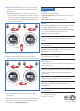
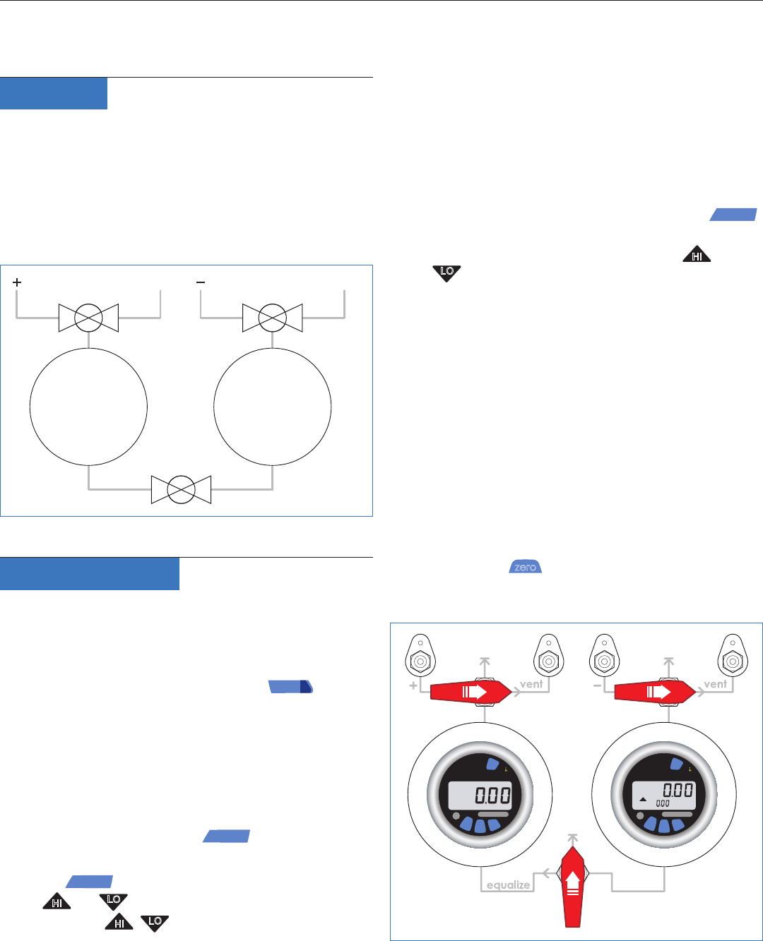
4 Zero Gauges: Zero both gauges in the vented condition
by pressing the
zero
button on each gauge. Figure 2
illustrates the appropriate valve states to ensure venting
and isolation between both gauges.
C R Y S T A L
XP
2
C R Y S T A L
XP
2
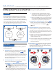
HI
Figure 1: General piping interconnect diagram.
Figure 2: Zero gauge valve states.
C R Y S T A L
engineering corporation
© 2007 Crystal Engineering Corporation 708 Fiero Lane, Suite 9, San Luis Obispo, California 93401-8701
Single-
or Dual-line
display
vent
vent
Dual-line
display
(Second line is
DP Measurement)