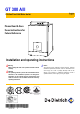
GT 300 A/II English Oil-Gas Fired Hot Water boiler 03/14/08 Please Read & Save these instructions for Future Reference Installation and operating instructions Warning: Before putting the boiler into operation read this manual carefully. Warning: The operating manual is part of the documentation that is delivered to the installation’s operator. Go through the information in this manual with the owner/operator and make sure that he or she is familiar with all the necessary operating instructions.
Guideline of Notices Warning: indicates presence of hazards that can cause, if not avoided, severe personal injury, death or substantial property damage. ! Caution: indicates presence of hazards that will or can cause, if not avoided, minor personal injury or property damage. Notice: Application comment for optimum use of equipment and adjustment as well as useful information. Safety Considerations Please observe the following safety instructions. Read this manual carefully.
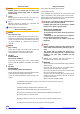
Contents Contents . . . . . . . . . . . . . . . . . . . . . . . . . . . . . . . . . . . . . . . . . . . . . . . . . . . . . . . . . . . . . . . . . . . . . . . . . . . . . . . . . . . .3 Regulations and guidelines . . . . . . . . . . . . . . . . . . . . . . . . . . . . . . . . . . . . . . . . . . . . . . . . . . . . . . . . . . . . . . . . . . . .4 Installation codes. . . . . . . . . . . . . . . . . . . . . . . . . . . . . . . . . . . . . . . . . . . . . . . . . . . . . . . . . . . . . . . . . . . . . . . .
Regulations and guidelines The installation and operating instructions shown here are given as a guide for installation and operation and are not meant to replace any State or Local Codes that may apply to the individual installation. Good engineering practice should be used. Any deviation from laws or regulations or industry Code or these instructions will void the boiler warranty and any other responsability or liability of the De Dietrich Thermiques S.A.
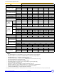
GT 300 A/II Technical Specification Table Model Item Unit GT 304 A/II GT 305 A/II [CSA] - # 2 Fuel Oil Input GT 307 A/II GT 308 A/II GT 309 A/II 1,226 1,442 Consult Burner Technical Data Firing Sequence [CSA] - Gas Input GT 306 A/II MBH 404 598 808 1,024 kW 118 175 237 300 359 423 US GPH 2.80 4.15 5.60 7.10 8.50 10.00 MBH 343 509 686 870 1,042 1,226 kW 100.6 149.1 201.2 255.1 305.3 359.
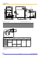
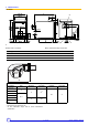
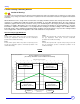
4 Main Dimensions GT 300 A/II A A C B D A Water flow tapping 2 1/2" NPSC C Drain 1 1/2" FPT B Water return 2 1/2" NPSC D Rp 2 1/2 diameter sludge removal hole Type of boiler GT 304 A/II GT 305 A/II GT 306 A/II GT 307 A/II GT 308 A/II GT 309 A/II L 385/8" 4459/64" 517/32 5733/64" 6313/16" 707/64" P 199/32 2519/32" 317/8 383/16" 4431/64" 5025/32" ØR 7" 7" 7" 8" 8" 8" G50_0001 X Dimension "X" Max.
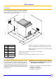
Boiler Installation 1 Installation The GT 300 A/II boiler has a base frame, although a housekeeping pad is recommended to keep steel parts out of casual water. Its furnace is closed, so it is not necessary to place it on a fireproof floor, but the floor must be able to bear the weight.
4 Main Dimensions GT 300 A/II A A C B D A Water flow tapping 2 1/2" NPSC C Drain 1 1/2" FPT B Water return 2 1/2" NPSC D Rp 2 1/2 diameter sludge removal hole Type of boiler GT 304 A/II GT 305 A/II GT 306 A/II GT 307 A/II GT 308 A/II GT 309 A/II L 385/8" 4459/64" 517/32 5733/64" 6313/16" 707/64" P 199/32 2519/32" 317/8 383/16" 4431/64" 5025/32" ØR 7" 7" 7" 8" 8" 8" G50_0001 X Dimension "X" Max.
Venting 5. . Boiler Venting & Chimney General Caution & Warning: It is advised and recommended that the heating contractor-professional apply vent materials that are approved and agency listed. Installation of any venting must follow all local codes in conjunction with vent manufacturer instructions and appliance manufacturer instructions. All De Dietrich GT series oil-gas fired cast iron boilers are high performance boilers that could operate under all 4 vent categories as established by ANSI Z21.
5.1 Boiler Venting – Category I & II Typical Layouts and Requirements. Caution & Warning: Improperly sealed venting system could result in carbon monoxide [CO] poisoning; ensure adequate support and fastening of the system. Ensure venting can safely exhaust all flue gases outside in an effective manner. These systems must operate under a negative vent pressure condition that is stable. Warning & Cautions for Co-Venting: Co-venting with other appliances shall conform latest ANSI Z223.
5.2 Boiler Venting – Category III & IV Vent Systems Typical Layouts and Requirements. Caution & Warning: Improperly sealed venting system could result in carbon monoxide [CO] poisoning; ensure adequate support and fastening of the system. Ensure venting can safely exhaust all flue gases outside in an effective manner. These systems must operate under a positive vent pressure condition that is stable. Warning & Cautions for Co-Venting: Co-venting with other appliances shall conform latest ANSI Z223.
5.3 Boiler Venting – Side-Wall or Direct Vent Systems Typical Layouts and Requirements. Caution & Warning: Improperly sealed venting system could result in carbon monoxide [CO] poisoning; ensure adequate support and fastening of the system. Ensure venting can safely exhaust all flue gases outside in an effective manner. These systems must operate under a positive vent pressure condition that is stable.
5.4 Boiler Venting – Side-wall or Direct Vent Systems Sizing Tables & Vent Safety Device • Vent termination must be a TEE type, follow warning regarding termination locations. Do not include the termination TEE length in the vent length calculation. • Venting shall be sloped, so any condensation developed will drain through the condensate TEE fitting Minimum vent length [equivalent] 5 ft. [1.5m] • Maximum number of 90° elbows = 2 or 3 45° elbows, each 90° elbow is equivalent to 10 ft.
5.5 All Side-wall and direct Vent termination locations installation precautions: Warning/Caution: In all cases avoid potential vent termination locations where excess debris or snow could accumulate and bock the vent termination to any degree. Minimum clearance of 4 ft. [1.22m] horizontally from, and in no case above or below, unless a 4 foot [1.22m] horizontal distance is maintained, from electric meters, gas meters, regulators & relief equipment.
6 Dimensional information required for connection of the boiler 15 5 "5 The boiler must be connected to venting system that will safely and effectively discharge all flue gases to the outside in an effective manner. /16 "11 /16 Consult local and national codes regarding the boiler breeching and chimney sizing.
Electrical 1 Wiring Wiring in accordance with the requirements of the authority having jurisdiction or, in the absence of such requirements, with the Canadian Electrical Code Part 1, CSA C22.1, Electrical Codes. Warning/Caution: Label all wiring prior to disconnection for servicing controls. Wiring errors can cause improper and dangerous operation. "Verify Proper Operation After Serving" 2 Wiring procedure De Dietrich boiler suggested field wiring procedure.
Boiler Control Wiring Flexible Eutectic Sales Ltd.
Electrical 1 Wiring Wiring in accordance with the requirements of the authority having jurisdiction or, in the absence of such requirements, with the Canadian Electrical Code Part 1, CSA C22.1, Electrical Codes. 2 Wiring procedure De Dietrich boiler suggested field wiring procedure.
FOR YOUR SAFETY READ BEFORE OPERATING If you do not follow these instructions exactly, WARNING: a fire or explosion may result causing properly damage, personal injury or loss of life. A. This appliance does not have a pilot. It is equipped with an ignition device wich automatically lights the burner. Do not try to light the burner by hand. B. BEFORE OPERATING smell all around the appliance area for gas. Be sure to smell next to the floor because some gas is heavier than air and will settle on the floor.
Maintenance 1 Boiler It is not advisable to drain an installation, except in case of absolute necessity. Check the water level of the installation and top it off if necessary, avoiding a sudden inlet of cold water in the hot boiler. Check for system leaks. Professional water treatment is recommended. The good performance of the boiler depends on cleanliness. Cleaning the boiler must be carried out as often as required and at least, as for the flue once a year.
- open the sweeping door (upper door) by unscrewing the 4 lock nuts. - also brush the convection baffles and the front face, - remove the convection baffles, - if possible use a vacuum cleaner, - using the brush supplied, carefully sweep the 6 flue sections, - put the convection accelerators back in place (pay attention to their direction), - shut the door.
Service and maintenance schedule `Require annul system inspection of the heating boiler, burner and controls by qualified service personnel, `Heating system check for safety control functions, system pressure, leaks, combustion and ventilation air should be done on a monthly schedule. Extended Shutdown Periods If the system is to be shutdown for any extended period of time, please follow these steps: 1. Shut off all pumps 2. Cap off venting of boiler at the boiler collars 3.
Spare parts - GT 300 A/II 06/10/06 - 8553-4312B While ordering spare parts, do not forget to provide the code number given opposite the part reference. BOILER BODY AND ACCESSORIES 19 16 18 11.1 20 16 7 1 16 2 6 4 11.2 7 16 3 10.2 11.3 16 15 14 13 10.1 17 12 29 12 30 16 24 17 51 28 8 50 32 5 31 8553N135 21 25.
BASE FRAME + INSULATION 24 GT 300 A/II 06/10/06 - 94863873 - 85534150E
CASING 25
CONTROL PANEL 140 143 149 147 142 150 146 143 145 150 5 6 3 4 7 8 148 9 5 6 3 4 7 8 9 151 141 144 151 152 12 11 VA 10 S3 T6 T2 T1 8 T7 9 T8 7 6 5 L1 153 153 : fasteners for control panel 26 GT 300 A/II 06/10/06 - 94863873 - 85534150E
Ref. Code no. DESCRIPTION Ref. Code no.
Ref. Code no.
GT 300 A/II 06/10/06 - 94863873 - 85534150E
www.dedietrichthermique.com www.dedietrich-boilers.
GT 300 A/II English Fuel oil/gas hot water boiler 02/12/07 Warning/Caution: Label all wiring prior to disconnection for servicing controls. Wiring errors can cause improper and dangerous operation.
Installation codes The boiler shall be assembled and installed by a qualified professional only. Strict compliance with these installation and operating instructions is a precondition for the correct and guarantee of the boiler. The installation must conform to the requirements of the authority having juristriction or, in the absence of such requirements, to the CAN/CGA B-149 fuel gas installation codes and CSA B-139 oil installation codes.
Packing For Canada: BOILER PACKAGED CONTENTS INCLUDED: • Installation and operating instructions • Assembly instructions • Tube(s) of silicone #9428-5095 • Can(s) of lubricant # 9430-5027 • Assembly tools # 8801-7000/7005 Packing : Before assembling the boiler, check with the chart below to make sure that you have all the component packages. 1.
Assembly GT 330 Tools required • Tube of silicon caurk • Side cutter (for cutting thermocord) • Wire brush (for cleaning section openings): use of a *1" fitting brush attached to cordless saves time. • Sand cloth (for cleaning nipples): Using a power brush saves time. • Solvent • Wooden or rubber mallet • Tightness sealant: See step 28 THESE TOOLS ARE IN ADDITION TO YOUR NORMAL TOOL REQUIREMENTS. some spare screws are provided.
1 FD30 - FD31 - FD32 - FD33 - FD34 - FD35 2 31/08/06 - /ND GT 300 A/II 5
3 4 6 GT 300 A/II 31/08/06 - /ND
5 85 53 N0 51 A (1) Glasspaper 6 (2) Lubricant (supplied) 31/08/06 - /ND GT 300 A/II 7
7 85 53 N0 12 8 (3) 1” 85 53 N1 28 A (3) Tube of silicon caurk (provided) 8 GT 300 A/II 31/08/06 - /ND
9 (1) Thermocord 10 31/08/06 - /ND GT 300 A/II 9
11 12 10 GT 300 A/II 31/08/06 - /ND
13 B 1” (1) Glasspaper (2) Lubricant (supplied) 31/08/06 - /ND GT 300 A/II 11
14 15 ø 7 1/2" Adjust the thermal insulation to match the burner.
16 B B A 4x A B B A B B B C A C M12 x 1"31/32 B 8x A C B C M12 x 3"5/32 C 85 53 N1 31 4x B M12 17 31/08/06 - /ND GT 300 A/II 13
18 19 14 GT 300 A/II 31/08/06 - /ND
20 8553N172 Desludging unit connection 31/08/06 - /ND GT 300 A/II 15
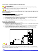
21 Combustion air supply must be provided according to national and local codes: CSA B149.1 -.2 & CSA B139 ANSI Z223.
22 Illustration above showing minimum distances to combustible materials and servicing. 8553N178B Boiler must not be installed on combustible material or on carpet.
23 8553N028 24 4x M8 18 GT 300 A/II 31/08/06 - /ND
25 (A) Thermocord 26 31/08/06 - /ND GT 300 A/II 19
27 Hydraulic test For USA: After assembling the boiler body, the installer must carry out a water tightness test at a pressure equal to 1.5 times the operating pressure (that is 108 PSI minimum) for 10 minutes at least. The test must be done at room temperature. For Canada: After assembling the boiler body, the installer must carry out a water tightness test at a pressure equal to 1.5 times the operating pressure (that is 81* PSI minimum) for 30 minutes at least. The test must be done at room temperature.
" $ % # 85 53 N1 34 & ' 251 USA: 108 PSI: Maintain pressure for at least 10 minutes. Canada: 81* PSI: Maintain pressure for at least 30 minutes. *: 59 PSI minimum in Alberta. Any drop in pressure indicates a leakage in the boiler body.
28 8553N114 B 2 3 A 1 5 GT306A/II GT307A/II GT308A/II 5 GT309A/II A. Drain tap (not supplied) B.
29 USA: FD182 - FD183 - FD184 - FD185 - FD186 - FD 187 Canada: FD1 - FD2 - FD3 - FD4 - FD5 - FD6 85 53 N1 32 4x 4x M12 x 1"37/64 6x 4x M8 x 0"15/32 4x M12 4x DEC M8 12x CBL 6x DEC M4 4x AZ 12 2x 12x 6x 4x M12 Lg.
31 8-9 section boilers 8553N116A 24 GT 300 A/II 31/08/06 - /ND
8553N117 32 31/08/06 - /ND GT 300 A/II 25
33 M12 8553N118 M12 M12 M12 34 26 GT 300 A/II 31/08/06 - /ND
35 M8 4 M8 M8 3 3 8553N119A 2 1 1 31/08/06 - /ND GT 300 A/II 27
36 2 2 1 2 85 53 N1 20 37 8553N121A 28 GT 300 A/II 31/08/06 - /ND
8553N173 38 " ! 120 V - 60 Hz 31/08/06 - /ND GT 300 A/II 29
39 Control panel assembly 5 85 3N 17 4 40 2 1 8553N054A 2 30 GT 300 A/II 31/08/06 - /ND
41 8553N122 3 1 2 Carefully unwind the sensor bulbs and pass them through the opening in the front top cover. Insert them into the one well and secure them with the spring. The extra well is for auxiliary high temperature limit with manual reset. 42 Make the electrical connections to the terminal strip provided inside the control panel. Close the control panel (2 self-tapping screws + lockwashers).
44 85 53 32 N1 24 GT 300 A/II 31/08/06 - /ND
45 1 1 2 2 85 53 31/08/06 - /ND N1 26 GT 300 A/II 33
46 A B A: Stick warning label B: Stick data plate 34 GT 300 A/II 31/08/06 - /ND
31/08/06 - /ND GT 300 A/II 35
The Manufacturer: Bp 30 – 57, RUE DE LA Gare F – 67580 MERTZWILLER Tel: +33/3/88/80/27/00 – Fax: +33/3 88 80 27 99 Ni IRC : 347 555 559 RCS STRASBOURG www.dedietrich-thermique.com DDR AMERICAS INC. In Canada: 1090 Fountain St., Unit #10 Cambridge, Ontario, N3E 1A3 - CANADA Tel: 519.650.0420 Fax: 519.650.1709 In USA or South America: 1054 North DuPage Avenue Lombard, Illinois, USA 60148 Tel: 630.953.2374 Fax: 630.953.2376 Toll Free 1.800.943.6275 www.dedietrichboilers.