
Specifications
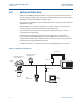
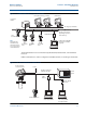

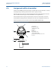

Table Of Contents
- Rosemount 5400 Series
- Section 1: Introduction
- Section 2: Transmitter Overview
- Section 3: Mechanical Installation
- 3.3.1 Mounting location 22
- 3.3.2 Special considerations in solids applications 24
- 3.3.3 Mounting in pipes 25
- 3.3.4 Installation considerations 26
- 3.3.5 Nozzle considerations 27
- 3.3.6 Nozzle recommendations and requirements 30
- 3.3.7 Service space 32
- 3.3.8 Beamwidth 33
- 3.3.9 Vessel characteristics 35
- 3.3.10 Disturbing objects 35
- 3.3.11 Valves 35
- 3.4.1 Cone antenna flange connection 36
- 3.4.2 Process seal antenna 37
- 3.4.3 Rod antenna threaded connection 38
- 3.4.4 Rod antenna flanged connection 39
- 3.4.5 Tri-Clamp™ tank connection 40
- 3.4.6 Bracket mounting on wall 41
- 3.4.7 Bracket mounting on pipe 42
- Section 4: Electrical Installation
- 4.3.1 Conduit electrical connector wiring (using minifast®) 45
- 4.7.1 Connecting the transmitter 47
- 4.8.1 Power requirements 49
- 4.8.2 Load limitations 49
- 4.8.3 Non-intrinsically safe power supply 51
- 4.8.4 Intrinsically safe power supply 52
- 4.8.5 Type N approvals: non-sparking / energy-limited power supply 53
- 4.8.6 Transient protection terminal block 54
- 4.9.1 Power requirements 55
- 4.9.2 Non-intrinsically safe power supply 57
- 4.9.3 Intrinsically safe power supply 58
- 4.9.4 Type N approvals: non-sparking / energy-limited power supply 59
- 4.10.1 Connecting the transmitter 60
- 4.10.2 Connection terminals 62
- 4.10.3 RS-485 bus 63
- 4.10.4 Installation cases 63
- 4.10.5 External HART devices (slaves) 65
- 4.11.1 Connect to the MA/MB terminals 66
- 4.11.2 Connect to the HART terminals 68
- 4.12.1 Tri-Loop™ HART to analog converter 69
- 4.12.2 751 Field Signal Indicator 70
- 4.12.3 Smart Wireless THUM™ Adapter 71
- Section 5: Basic Configuration/Start-up
- 5.2.1 Basic configuration parameters 74
- 5.2.2 Configuration tools 74
- 5.3.1 Measurement units 75
- 5.3.2 Tank geometry 75
- 5.3.3 Process conditions 77
- 5.3.4 Volume configuration 78
- 5.3.5 Analog output (HART) 81
- 5.3.6 Level and distance calibration 82
- 5.3.7 Echo tuning 83
- 5.3.8 ATC 84
- 5.4.1 System requirements 84
- 5.4.2 Help in RRM 85
- 5.4.3 Installing the RRM software for HART communication 85
- 5.4.4 Specifying the COM port 87
- 5.4.5 To set the COM port buffers 88
- 5.4.6 Specifying measurement units 88
- 5.4.7 Installing the RRM software for Foundation fieldbus 88
- 5.4.8 Specifying measurement units 90
- 5.4.9 Using the Setup functions 91
- 5.4.10 Guided setup 92
- 5.4.11 Using the Setup functions 100
- 5.8.1 Advanced configuration 111
- 5.9.1 Assigning device tag and node address 113
- 5.9.2 Foundation fieldbus block operation 113
- 5.10.1 Radar level transmitter - level value 115
- 5.10.2 Radar level transmitter - level value in percent (%) 116
- Section 6: Operation
- Section 7: Service and Troubleshooting
- 7.3.1 Analyzing the measurement signal 132
- 7.3.2 Surface pulse not found 133
- 7.3.3 Registration of false echoes 135
- 7.3.4 Using the Echo Curve Analyzer 137
- 7.3.5 Using the Echo Curve Analyzer with a Field Communicator 140
- 7.14.1 Troubleshooting 153
- 7.14.2 Device status 153
- 7.14.3 Errors 154
- 7.14.4 Warnings 155
- 7.14.5 Measurement status 155
- 7.14.6 Volume calculation status 157
- 7.14.7 Analog Output status 158
- 7.14.8 Application errors 159
- 7.15.1 Resource block 164
- 7.15.2 Transducer block 165
- 7.15.3 Analog Input (AI) function block 165
- Section 8: Safety Instrumented Systems (4-20 mA Only)
- 8.2.1 Applicable models 168
- 8.2.2 Skill level of personnel 169
- 8.5.1 Damping 171
- 8.5.2 Alarm and saturation levels 171
- 8.5.3 Amplitude threshold 172
- 8.5.4 Write protection 172
- 8.5.5 Site acceptance 172
- 8.6.1 General 172
- 8.6.2 Inspection 173
- 8.7.1 Specifications 174
- 8.7.2 Failure rate data 174
- 8.7.3 Useful lifetime 174
- A.1.1 General 177
- A.1.2 4-20 mA HART® (output option code H) 178
- A.1.3 Foundation™ fieldbus (output option code F) 181
- A.1.4 RS-485 with Modbus communication (output option code M) 183
- A.1.5 Display and configuration 185
- A.1.6 Diagnostics 186
- A.1.7 Temperature and pressure limits 187
- A.2.1 General 189
- A.2.2 Measuring range 190
- A.2.3 Beam angle and beam width 191
- A.2.4 Transition zone and near zone 193
- A.2.5 Environment 194
- A.3.1 Material selection 195
- A.3.2 Housing and closure 195
- A.3.3 Engineered solutions 196
- A.3.4 Tank connection and antennas 196
- A.4.1 Rosemount 5402 and 5401 with SST Cone Antenna (Model Code: 2S-8S) 200
- A.4.2 Rosemount 5402 and 5401 with Protective Plate Cone Antenna (Model Code: 2H-8H, 2M-8M, and 2N-8N) 201
- A.4.3 Rosemount 5401 with Rod Antenna (Model Code: 1R-4R) 202
- A.4.4 Rosemount 5402 with Process Seal Antenna (Model Code: 2P-4P) 203
- A.4.5 Bracket mounting (Model Code: BR) 204
- A.4.6 Process connections 205
- B.5.1 North-American certifications 220
- B.5.2 Canadian Standards Association (CSA) Approvals 221
- B.5.3 European certifications 222
- B.5.4 IECEx Approval 224
- B.5.5 EAC certifications 225
- B.5.6 Brazilian certifications 226
- B.5.7 Chinese certifications 226
- B.5.8 Japanese certifications 227
- B.5.9 Other certifications 228
- B.5.10 Canadian Registration Number (CRN) 229
- C.1.1 Distance offset (G) 237
- C.1.2 Minimum level offset (C) 238
- C.1.3 Hold off distance 238
- C.1.4 Calibration distance 238
- C.3.1 Antenna type 239
- C.3.2 Empty tank handling 239
- C.3.3 Full tank handling 241
- C.3.4 Double bounce 241
- C.3.5 Surface echo tracking 242
- C.3.6 Filter settings 243
- C.4.1 Empty tank handling 243
- C.4.2 Full tank handling 247
- C.4.3 Double bounce 248
- C.4.4 Surface echo tracking 249
- C.4.5 Hold off setting 250
- E.1.1 Definition 257
- E.1.2 Channel definitions 257
- E.3.1 Unit codes 263
- F.1.1 Register access transducer block parameters 265
- G.1.1 Advanced configuration transducer block parameters 269
- H.2.1 PlantWeb® alerts 278
- H.2.2 Alarm priority 281
- H.2.3 Recommended actions for PlantWeb alerts 282
- I.6.1 Status handling 292
- Section 1 Introduction
- Section 2 Transmitter Overview
- Section 3 Mechanical Installation
- Section 4 Electrical Installation
- Section 5 Basic Configuration/Start-up
- 5.1 Safety messages
- 5.2 Overview
- 5.3 Basic configuration parameters
- 5.4 Basic configuration using RRM
- 5.5 Configuration using a Field Communicator
- 5.7 Basic configuration using AMS Suite
- 5.8 Configuration using DeltaV
- 5.9 Foundation fieldbus overview
- 5.10 Application examples
- 5.11 Tri-Loop™ HART to Analog Converter
- 5.12 HART multidrop configuration
- Section 6 Operation
- Section 7 Service and Troubleshooting
- 7.1 Safety messages
- 7.2 Troubleshooting overview
- 7.3 Service overview
- 7.4 Analog Output calibration
- 7.5 Logging measurement data
- 7.6 Backing up the transmitter configuration
- 7.7 Diagnostics
- 7.8 Configuration report
- 7.9 Viewing input and holding registers
- 7.10 Reset to factory settings
- 7.11 Surface search
- 7.12 Using the Simulation Mode
- 7.13 Write protecting a transmitter
- 7.14 Diagnostic messages
- 7.15 Troubleshooting
- Section 8 Safety Instrumented Systems (4-20 mA Only)
- Appendix A Reference Data
- Appendix B Product Certifications
- Appendix C Advanced Configuration
- Appendix D Performing Proof Test
- Appendix E Level Transducer Block
- Appendix F Register Transducer Block
- Appendix G Advanced Configuration Transducer Block
- Appendix H Resource Block
- Appendix I Analog-Input Block
11
Reference Manual
00809-0100-4026, Rev HA
Section 2: Transmitter Overview
November 2014
Transmitter Overview
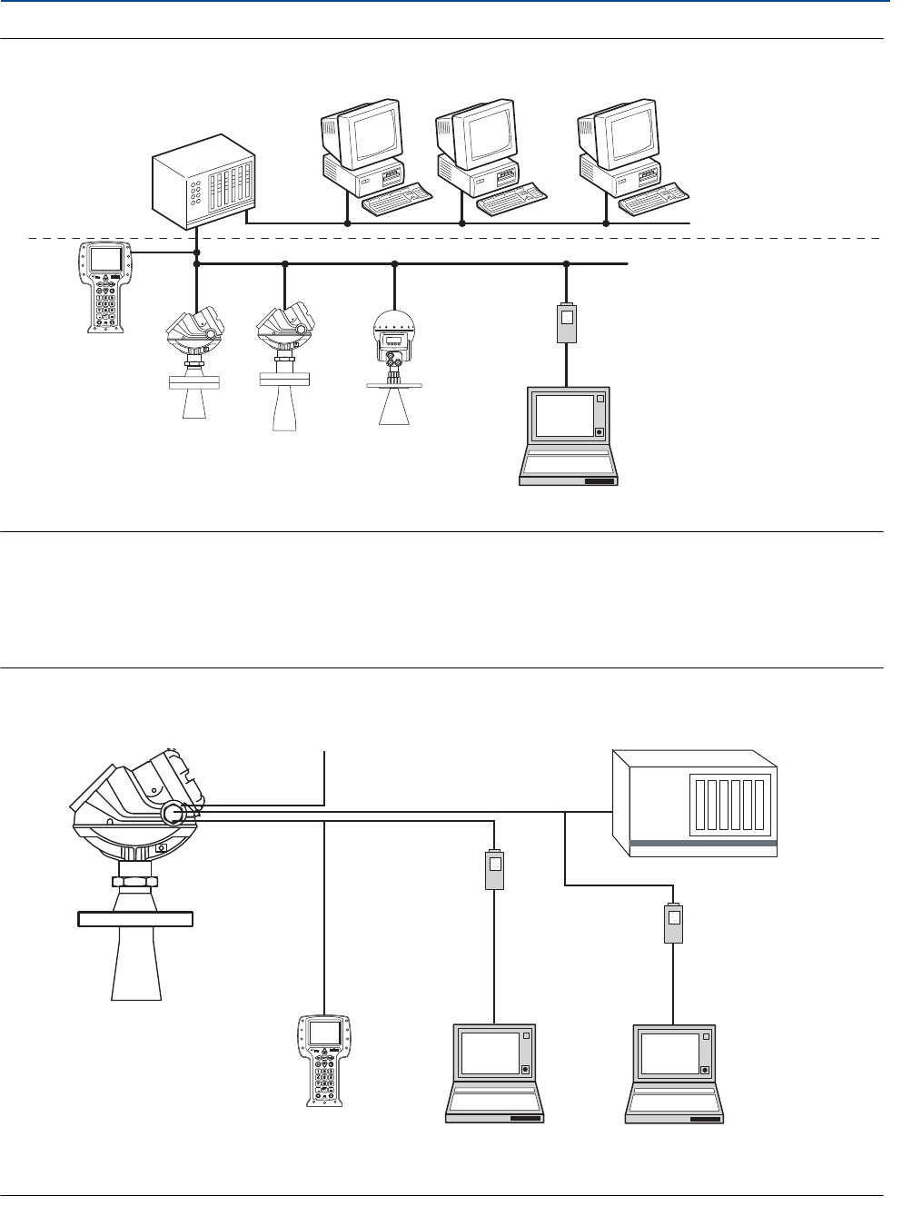
Figure 2-3. FOUNDATION fieldbus System Architecture
The RS-485 Modbus version communicates by Modbus RTU, Modbus ASCII, and Level Master
Protocols.
HART communication is used for configuration via HART terminals, or tunneling via the RS-485.
Figure 2-4. RS-485 with Modbus Communication
FOUNDATION
fieldbus
Note
Intrinsically safe
installations may
allow fewer devices
per I.S. barrier due to
current limitations.
Host / DCS system (e.g. DeltaV)
Maintenance
Field
Communicator
Rosemount
5401
Rosemount
5402
Rosemount
5601
Fieldbus Modem
H1 - Low Speed Field Bus
6200 ft (1900 m) max
(depending upon cable
characteristics)
Configuration with RRM
(hooked up on Fieldbus
segment)
H2 - High Speed Field Bus
Rosemount 5400
Series Transmitter
HART
Modem
Power
Modbus, Levelmaster
Emulation / RS-485
Control
System
RS-232 / RS-485
Converter
PC
5400 Setup in RRM
PC
5400 Setup in RRM
through Tunneling
Field Communicator