
User`s guide

21-0381E v4.7.3
Welcome Report Control Admin
Sys Config Tech-Ref
279
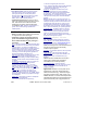
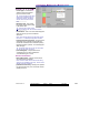
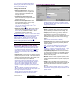
Circuit 1, 2, 3, or 4 )
- Circuit Type: This allows
selecting from the supported
types of custom circuits;
Tip: The circuit-type that you select
will be shown graphically near the
middle of the screen, and default
resistor values are shown farther
down.
-------------------------
- [Reset Circuit]: This reverts
the present circuit number (tab)
to its default value.
Tip: This is the same value as with
older-style modules, and ≤V4.3 Director software.
-------------------------
- Circuit Name: This is the name that will appear
when this circuit type is to be selected
elsewhere.
Note: Since this will appear on keypad LCD screens,
this can be 1 - 12 letters (all caps) and/or numbers.
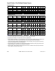
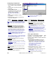
- (Coloured bands and legend): This shows the
calculated range of actual circuit resistances
that will be considered as normal state (Green),
tampered condition (Yellow), or in-alarm/tripped
state (Orange);
Tip: The values shown here are for your information
only (do not enter them anywhere).
- (Circuit Diagram): This provides visual
confirmation that you have selected the
correct/desired type of circuit;
End of Line Resistors
- EOL R1/R2 (ohms): Custom resistor values
are entered here (if needed);
Note: Enter the actual value for each resistor being
used (not any calculated circuit value). See the circuit
diagram for resistor orientation.
- [Calculate Thresholds]: Clicking here updates
the coloured bands for your new resistor values
(details previous).
Configuration, ÖInput Points, ÖCustom Circuit