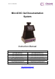
Version: Jun2014/G16 MicroDOC Gel Documentation System Instruction Manual Model Numbers: CSL-MICRODOC CSL-MICRODOC1D CSL-MDOCUV312 CSL-MDOCUV3121D CSL-MDOCUV254 CSL-MDOCUV2541D CSL-MDOCUV365 CSL-MDOCUV3651D CSL-MDOCUV254/312 CSL-MDOCUV254/3121D CSL-MDOCUV254/365 CSL-MDOCUV254/3651D CSL-MDOCBASIC CSL-MDOCBASIC1D www.cleaverscientific.com info@cleaverscientific.
Packing list MicroDOC (all models except CSL-MDOCBASIC/1D): -1x Canon PowerShot G16 Digital Camera Package (Includes all accessories and manuals) -1x Camera DC Coupler -1x 4GB Memory Card -1x Memory Card Reader -1x Lens Adapter -1x 8” TFT Colour Screen -1x Hood -1x (+3) Close-up Lens -1x Ethidium Bromide or SYBR Green Filter -1x Power Cord -1x US Plug Power Cord for hood and UV transilluminator connection -1x MicroDOC System Instruction Manual Product Specification (CSL-MDOCBASIC/1D) -1x Canon PowerShot G1
Table of Contents Packing list ………………………………………………………………………1 Table of Contents........................................................................................... 2 Section 1 Warning ................................................................................. 3 Section 2 Introduction ........................................................................... 6 2.1 Overview ..................................................................................................... 6 2.
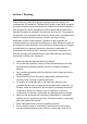
Section 1 Warning Cleaver Scientific’s MicroDOC System has been tested and found to be compliant with CE regulations. The MicroDOC System is also RoHS compliant and meets with all environmental directives. These limits of RoHS compliance were designed to provide reasonable protection against harmful interference when the equipment is operated in a commercial environment.
shock hazard. 9. The unit should only be operated by qualified personnel. 10. It is strongly recommend that the user wears UV protection equipment when operating the MicroDOC System. Warning: High Ultraviolet Radiation! Safety Information Before connecting to the electrical supply, check the supply voltage is within the range stated at the rating label, and that the device is earthed. Place the unit in a safe and dry location. Also follow any safety precautions for chemicals and/or dangerous materials.
5. ONLY connect the power supply to a properly grounded AC outlet. Avoiding Damage to the Instrument 1. Do not attempt to operate the device if it is damaged. 2. Protect this unit from source of physical damage, corrosive agents and extreme temperatures (direct sunlight etc). 3. To ensure proper ventilation and safety, retain at least 10 cm of space behind the instrument and at least 5 cm of space on each side. 4.
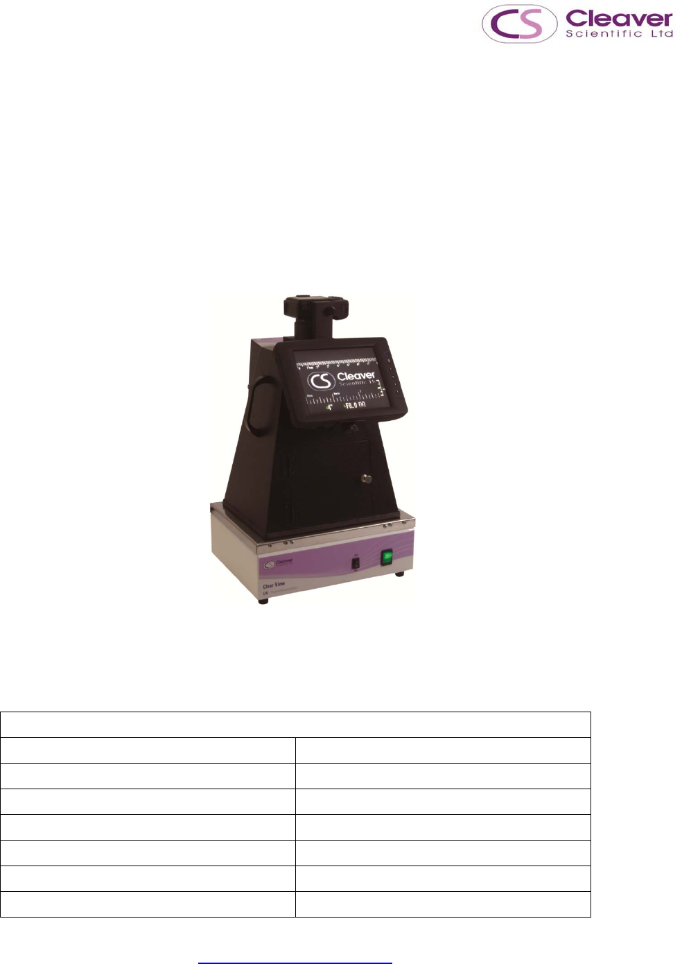
Section 2 Introduction 2.1 Overview The Cleaver Scientific MicroDOC is a user-friendly gel documentation system with 12.1 mega pixel high resolution camera. A large 8” TFT screen enables images, including agarose and fluorescent gels, colorimetric gels, autoradiography film and blotting membrane, to be captured in colour, clearly and easily. The system is computer free and supplied with a 4GB storage card and 55mm ethidium bromide filter as standard, while an optional SYBR filter is also available.
2.
MicroDOC Hood Control Panel 1. – White light power switch 2. – UV light power switch 3.
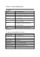
Section 3 Technical Specifications 3.1 Camera Camera Canon PowerShot G16 Effective Pixels Approx. 12.1 megapixels CMOS 1/1.7-inch type CMOS; Approx. 12.1 million pixels Image Resolution 640 x 480 up to 4,000 x 3,000 Lens 6.1 (W) – 30.5 (T) mm (35mm film equivalent: 28 (W) - 140 (T) mm) F / -Number f/1.8 (W) - f/2.8 (T) File Format Design rule for Camera File system, DPOF (version 1.1) compliant Data Type Still images: Exif 2.
Section 4 Installation Instructions Cleaver Scientific’s MicroDOC System is factory preinstalled instrument. Locate the microDOC on a sturdy, level dry surface, and UV transilluminator before operation. See the assembly procedure below. 4.1 Assemble the MicroDOC System 1. Fix Monitor 2. Connect Cable 3. Press ring release button and remove the ring 4. Prepare lens adaptor 5. Fix lens adaptor to camera 6.
7. Fit close-up lens to lens adaptor 8. Prepare EtBr or SYBR Green filter 9. Fit EtBr or SYBR Green filter on top 10. Insert power cable to the camera adaptor on the chamber DC coupler 11. Insert camera DC coupler until it locks, then close the cover 12. Fix camera to the camera adaptor on the chamber 13.
4.
B) C) 13
4.3 Preparing the Camera Before installing the camera, please review all function keys in Section 4.2 Camera Set-Up Menu. Install the DC Coupler as shown below (Installing the DC Coupler is necessary, because the MicroDOC System connects to the camera DC coupler, and provides DC power for camera use). Install the SD card as shown below. The date and time setting screen will appear when using the camera for the first time.
15
4.3.1 Camera Shooting Menu 8. 9. Press the power button to turn on the camera. This camera has three custom modes (C1, C2, and M) which could be selected via Mode dial Switch. It allows three different custom settings to be saved. We advise setting C1 mode for black& white photo and M mode for color photo. 4.3.2 Setting M Mode (for Color photo) Mode dial 10. Use the mode dial to switch to M. 11.
Custom Disp. --- Reverse Disp. ON IS Mode Continuous Converter NONE Date Stamp OFF/Date/Date & Time Set --- Func. Set Shortcut Button ---- Save Setting C1 Set Shortcut Button --- Set the movie button… --- Menu Item Setting Auto Power Down Off Display Off 3 min. 1.Turn the [ Item Setting Shutter Speed 1 sec ]dial to set shutter speed 12.
14. Press FUNC.SET( ) Button to change photo color as follows 1 2 Note: It is unnecessary to press FUNC.
15. Press MENU ( ) button to Save Settings to C1 4.3.4 Setting Shutter Speed 16. To adjust the shutter speed, turn the Front Dial located in the front of the camera 17. Shutter speed ranges from 1/2000 to 15” 18. 2” indicates 2 seconds 19.
4.3.5 Setting Aperture Value 20. Use the Control Dial to adjust 21. Aperture Value is expressed as F-stop (e.g. F2.8). The smaller the F-stop number, the larger the aperture (lens opening). Aperture Value ranges from F1.8 to F8.0 DNA Sample F2.8 Protein Sample F2.8 Western Blot F2.8 Radiographic Film F2.8 4.3.6 Setting Metering Mode There are three metering modes: 4.3.
. ISO value ranges from ISO 80 - 12800, and Auto. 23. Raising ISO value will increase the brightness of the fluorescent signal. However, the image will get course with increasing ISO value. High ISO value should be set only for gels with very weak signal. 4.3.8 Adjust the focal frame and focus mode When zoomed in beyond 5cm-∞ the camera may experience hardship auto focusing. It is recommended to switch to manual focus mode in these instances to acquire a better image. 24.
B. choose Manual Focus〈MF〉 C. Preferring to the on-screen MF Indicator bar and the magnified display area, press the buttons or turn the dial to specify the general focal position, and then press the button. 4.4 Sending images to the computer via Wi-Fi 1 Check the computer environment ○ The camera can connect via Wi-Fi to computers running the following operating systems.
2 Install CameraWindow on the computer ○ To save images to the computer wirelessly, users must install CameraWindow, which can be acquired from Service & Support page in Canon Official Website. 2-1 Download the software y y y With a computer connected to the internet, and access http://www.canon.com/icpd/. Access the site and select the country or region. Enter “Drivers & Software” page. Input the camera model name: PowerShot G16 y Unfold “Software” and download “CameraWindow”.
3 Configure the computer for the Wi-Fi connection (Windows only) ○ y y y Confirm that the computer is connected to the access point. Configure the setting by clicking the following order: [Start] menu > [All Programs] > [Canon Utilities] > [CameraWindow] > [Wi-fi connection setup] Open the application, then follow the on-screen instructions to configure the setting. ∗ The following Windows settings are configured when users run the utility in above steps. - Turn on media streaming.
This will enable the camera to see/find the computer to access via Wi-Fi. - Turn on network discovery. This will enable the computer to see/find the camera. - Turn on ICMP (Internal Control Message Protocol). This allows users to check the network connection status. - Enable Universal Plug & Play (UPnP). This will enable network devices to detect each other automatically.
4 Connect via an access point ○ Confirm that the Wi-Fi router or base station conforms to the Wi-fi standards of PowerShot G16. Then confirm the following items for network settings. ∗ Connection methods vary depending on whether the access point supports Wi-Fi Protected Setup (WPS) or not. Refer to the user manual provided with your access point to check if it supports WPS. 4-1 Connect to WPS-compatible access points y Confirm that the computer is connected to the access point.
- Press button to access the keyboard, and then enter a nickname. Up to 16characters can be used. - Press buttons or turn the dial to choose [OK], and then press button. Then the Wi-Fi menu is displayed. - Choose the target device, and then press - To connect to a computer, choose . - Press dial to choose [Add a buttons or turn the Device], and press - Press button. button. buttons or turn the dial to choose [WPS buttons or turn the dial to choose [PBC Connection].
∗ If users choose [PIN Method], a PIN code will be displayed on the screen. Be sure to set this code in the access point. Choose a device in the [Select a Device] screen. - On the access point, hold down the WPS connection button for a few seconds. - On the camera, press button. The camera will connect to the access point. - Press buttons or turn the computer name, and then press - dial to choose the button.
Double-click the connected camera icon to install the driver. After driver installation is complete, and the camera and computer connection is enabled, the AutoPlay screen will be displayed. Nothing will be displayed on the camera screen. *If users use Macinstosh computer, please skip this step. 4-2 Connect to access points in the list y Confirm that the computer is connected to the access point. y Access the WiFi menu on the camera. - Turn on the camera and press - Press button.
- Press buttons or turn the dial to choose [OK], and then press button. Then the Wi-Fi menu is displayed. - Choose the target device, and then press - To connect to a computer, choose . - Press dial to choose [Add a buttons or turn the Device], and press - Press button. buttons or turn the (access point), and then press - Press button. dial to choose a network button. button to access the keyboard, and then enter the password.
- Press press - Press buttons or turn the button. buttons or turn the computer name, and then press - dial to choose [Auto], and dial to choose the button. If the computer is running Windows for the first time, users will need to install a driver. When the screen at below is displayed on the camera, click the Start menu on the computer, then click [Control Panel], and click [Add a device]. Double-click the connected camera icon to install the driver.
5 Save images to a computer ○ When sending images to a computer, use the computer instead of the camera. y When the camera is connected to the computer, the camera screen is blank. Display CameraWindow on the computer. *On Macintosh computer, CameraWindow is automatically displayed when a Wi-Fi connection is established between the camera and computer. y y * Click [Import Images from Camera], and then click [Import Untransferred Images].
4.5 Install the UV Transilluminator Caution: UV transilluminator is a powerful source of UV radiation which will cause damage to unprotected eyes and skin. Before operating the UV transilluminator ensure that all personnel in the area are properly protected. It is preferable that the UV transilluminator is installed and operated in a darkroom where access and exposure is limited while the unit is in operation. Each UV transilluminator is equipped with an UV shield.
Section 5 Operation Instructions The unique feature of the Canon PowerShot G16 is that before capturing an image, it is possible preview the image from the display while simultaneously changing the shutter speed, aperture or ISO value. 5.1 DNA Sample Imaging 1. 2. Turn on the main power and switch on the white light Turn on the camera 3. 4. Switch the mode dial to C1 (Black/White photo) mode Open the Hood door. (The door contains a safety switch, the UV 5. 6. 7. 8.
(Section 4.2 B). The AF frame will display in green. Move the AF frame over the most prominent band by using the control dial. 15. Change the manual focus mode. When zoomed in beyond 5cm-∞ the camera may experience hardship auto focusing. It is recommended to switch to manual focus mode〈MF〉(4.3.8 Adjust the focal frame and focus mode) 16. Focus (Section 4.2 A): Press the shutter button halfway to set focus and exposure. And then press shutter bottom fully to take the picture. 17.
5.2 Protein Sample Imaging 1. 2. 3. 4. 5. Disconnect the wire cable between hood and UV transilluminator (Please make sure that the UV transilluminator is OFF). The hood has two built-in white light LEDs. Use these inner light LEDs as the light source for this application. Use the mode dial to switch to M (for colour image) Keep the aperture set on F2.8, change the Shutter Speed from 1/10, 1/20, 1/30. Use the DNA sample imaging procedure (Section 5.1 step 9 – 20) for protein sample image capture. 5.
Section 6 Trouble‐shooting guide Many operating problems may be solved by carefully reading and following the instructions in this manual accordingly. Some suggestions for troubleshooting are given below. Should these suggestions not resolve the problem, please contact our SERVICE DEPARTMENT or a distributor in your region for assistance. If troubleshooting service is required, please include a full description of the problem. Screen does not light Check if the mains power switch is on.
Section 7 Ordering Information Gel Documentation System System only System With 1D Software Compact Gel documentation system CSL-MICRODOC CSL-MICRODOC1D microDOC System with UV Transilluminator CSL-MDOCUV312 CSL-MDOCUV3121D CSL-MDOCUV254 CSL-MDOCUV2541D CSL-MDOCUV365 CSL-MDOCUV3651D CSL-MDOCUV254/312 CSL-MDOCUV254/3121D CSL-MDOCUV254/365 CSL-MDOCUV254/3651D CSL-MDOCUV312/365 CSL-MDOCUV312/3651D CSL-MDOCBASIC CSL-MDOCBASIC1D (UVT312) microDOC System with UV Transilluminator (UVT254) mic
Section 8 Warranty Cleaver Scientific Limited guarantees products of its manufacture against defects in materials and workmanship, under normal service, for one year from the shipping date to purchaser. This warranty excludes damage resulting from shipping, misuse, carelessness, or neglect. Cleaver Scientific Limited’s liability under the warranty is limited to the receipt of reasonable proof by the customer that the defect is covered within the terms of the warranty.