
Product specifications


Chapter 6. SNMP Option
63
May 2011
Chapter 6. SNMP Option
6.1 Installation
Installation of the SNMP optional feature should be performed by qualified service personnel
only. As with all electronic devices that are powered from an AC line, dangerous voltages may be
present inside the unit. The technician should exercise proper care and judgment. Only open the
unit for service after disconnecting the unit from the power source.
This documentation will explain in detail the proper procedure for installation of the SNMP
printed circuit board feature for the ETU01-A. This procedure may also require replacement of the
operational firmware for older versions of the ETU01-A as the older firmware does not support the
newer SNMP card functions.
6.1.1 Required tools and supplies
No.2 Philips head screwdriver
thread lock compound (such as Glyptol™)
small, flat blade screwdriver (to aid in replacing firmware IC)
6.1.2 Procedure (Please refer to the attached drawing)
Inspect the contents of the SNMP kit. It should contain one(1) SNMP card, three(3) brass
standoffs, six(6) 3mm screws, MIB file on CDROM, and possibly a 32pin EEPROM.
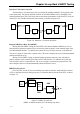
From the rear of the unit, disconnect all power, data port, and E1 cabling from the unit. Loosen
the two captive thumb-screws located on the lower left and right of the unit. Carefully slide the
mother PCB out of the case and place on a flat, clean work area. (Refer to Figure 6-1: Firmware
Chip Location.)
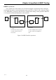
Refer to Figure 6-2, the SNMP Exploded view. Apply thread-lock to three mounting screws
and attach the three brass standoffs to the main PCB as shown. The standoffs are to be located on
the component side of the main PCB.
If the firmware needs to be upgraded, perform this step prior to insertion of the SNMP card.
Use a flat-blade screwdriver to carefully remove the EEPROM IC from PCB location U4 (refer to
Figure 6-1). Ensure that the pins of the new IC are straight, align the pins with the IC socket and
carefully seat the new IC. Excessive force should not be required. Inspect all 32 pins to ensure
proper seating and that no pins were inadvertently bent during insertion.
Install the SNMP pc board by aligning the pins of the SNMP card with the 20pin connector
and seat the card. Ensure that no pins are bent and that all pins have been received into the
connector socket on the main PCB.
Use the remaining 3mm screws to hold down the SNMP card. Do not over-tighten, just tighten
snug. Apply Glyptol™ to the hold down screws at your discretion. Refer to the exploded view
Figure 6-2.
If the system firmware has been replaced, a system reset will be required to initialize the
system properly. Return the motherboard to the case, tighten the captive thumb-screws and re-
attach all cables and power. Perform a system reset followed by re-configuration and normal loop
back diagnostics. Please refer to Chapter 3 if using the LCD or Chapter 4 for serial terminal.