
Specifications
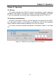


Chapter 3. Operation
22
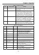
Table 3.1 Control Functions
Item Control Switch Function
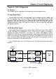
1 Loc dig loopbk The local digital loop back switch causes the
local ETU01-Plus to loop E1 received data to
its transmitter.
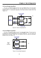
2 Loc ana loopbk The local analog loop back switch causes the
local ETU01-Plus to loop transmitter output
back to its receiver. The transmitter sends 'all
ones' data to the line. This loop back may also
be activated from the DTE when the data port
loop back test function is set to ENA (enable).
3 Rem loopbk The remote loop back switch causes the
remote ETU01-Plus to loop E1 received data to
its transmitter. This loop back may also be
activated from the DTE when the data port loop
back test function is set to ENA (enable).
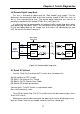
4 Pattern The pattern switch causes the ETU01-Plus to
send and receive a 511 test pattern. If errors
are encountered, the Error LED indicator lights.
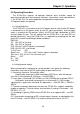
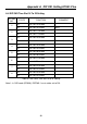
Table 3.2 LED indicators
Item Indicator Color Meaning
1 PWR Green ON when power is on.
2 TD Green ON when SPACE is being transmitted.
Flashing when data is transmitted.
3 RD Green ON when SPACE is being received.
Flashing when data is received.
4 RTS Green ON when terminal activates Request To
Sent.
5 DCD Green ON when a valid receive signal is present.
6 Tx CLK Loss Red ON when transmitted clock is lost.
7 Signal Loss Red ON when received signal is lost.
8 Sync Loss Red ON when received frame sync is lost.
9 Alarm Red ON when E1 link has an alarm. (Include:
BPV error / CRC4 error /
Frame slip / All ones / Remote alarm).
10 Error Red ON when Pattern switch is activated and bit
errors are detected.
11 Test Red ON when the ETU01-Plus is in any loop
back mode or Pattern is depressed.