USER MANUAL Series 4200E Part Number 91-601-01 Firmware Release 1.00 Ctek - Innovating Wireless Value .
Part Number 91-601-01 Release 1.00 Table of Contents TABLE OF CONTENTS I PREFACE 1 1 1 INTRODUCTION 1.1 Theory Of Operation 1 1.2 Features 1 2 CONNECTORS, LIGHTS, SWITCHES, AND JUMPERS 3 2.1 Switches 3 2.2 Lights 3 2.3 Connectors 5 START UP 6 3 3.1 Power 6 3.2 Connecting The Antenna 6 3.3 Connecting to the Ethernet Port – Administrative Connection 6 4 4.1 ADMINISTRATION, CONFIGURATION AND STATUS Getting Started 8 8 4.2 Interfaces 4.2.
Part Number 91-601-01 Release 1.
Part Number 91-601-01 Release 1.00 Preface Welcome to the Ctek Series 4200E SkyRouter User’s Guide. The User’s Guide will explain the basic operation of a SkyRouter and take you through the necessary settings to get your wireless application online. Additional information and applicable technical notices can be found at www.ctekproducts.com. 1 Introduction SkyRouter provides application and network designers with a bridge between the world of IT infrastructure and the evolving wireless data networks.
Part Number 91-601-01 Release 1.00 4) Relay Driver Output a. SMS Activation b. Web Activation 5) General Administration a. Modify Password 6) Status – Ethernet Status a. Currently Assigned IP Address b. Current MAC Address 7) Status – CDMA Status a. ESN (Serial Number) Hex and Decimal b. Network Assigned IP Address c. Telephone Number (MIN) d. Current Network Status Active/Inactive e.
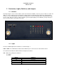
Part Number 91-601-01 Release 1.00 2 Connectors, Lights, Switches, and Jumpers 2.1 Switches Referring to Figure 1, there are two switches on the front of the Series 4200E. S1 (Reset) causes a hard reset of unit. S2 (DFLT) is used to completely restore the firmware settings that were included when the product was shipped from the factory. To restore factory defaults, the unit must be running. Press the Restore Defaults (inner) switch and hold it down for 10 seconds.
Part Number 91-601-01 Release 1.00 Link - Multi-color (red/green). Indicates: a) Status of IP connection b) Type of transport (EV-DO or 1xRTT) Display Definition Off Green Red No Connection (IP address) Connection established on 1xRTT Connection established on EV-DO Note – Early production units (serial number less than 0603051-010) have a different LED display. No service: Green off. Yellow on. In service, signal less than -88, no connection: Green LED off but does one short blink on every 4.5 seconds.
Part Number 91-601-01 Release 1.00 2.3 Connectors Ethernet Connectors Connectors are found on the back of the Series 4200E SkyRouter. Ethernet ports 1 – 4 are auto polarity sensing and can be used with either a standard Ethernet cable or a reverse (cross over) Ethernet cable. Terminal Block Connector J1 supports four separate functions, power, relay contact closure detection, relay driver output, and application port serial data. Contact closure pins 2 and 4 are shared with the application serial port.
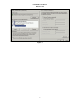
Part Number 91-601-01 Release 1.00 3 Start Up Warning – You must connect antennas to the SMA style antenna connectors on the SkyRouter before turning it on. Failure to do this could result in erratic start up behavior and could possibly damage the unit. Note – The 4200 SkyRouter ships from the factory with its DHCP server enabled. The Default Gateway address for the unit is 192.168.1.10. The address of the web based administration is also 192.168.1.10.
Part Number 91-601-01 Release 1.
Part Number 91-601-01 Release 1.00 4 Administration, Configuration and Status About Addressing – Devices connecting to CDMA/1XRTT networks are assigned an IP address by the serving network. Address assignment may either be static or the unit will be dynamically assigned an IP addresses, depending on arrangements that you have made with your wireless network operator.
Part Number 91-601-01 Release 1.00 Figure 5 Note that the administration menu is divided into three sections. The Interfaces section deals with physical connectivity, managing the connection and subtended devices. Services are applications that are within the router core to modify the behavior of a specific interface or to change system wide parameters within the router core. Status screens are provided for the CDMA ED-DO/1XRTT and Ethernet interfaces.
Part Number 91-601-01 Release 1.00 Figure 6 Network Select – (Note: This setting should only be changed after consulting with Ctek Support.) This pull down menu allows the user to control the home network setting of the CDMA connection, effectively limiting the scope of the Preferred Roaming List (PRL) assigned by your wireless network operator. The possible settings are shown below: User Name and Password – Required for activation on some networks. See TechNotes for specific usage.
Part Number 91-601-01 Release 1.00 Disabled – Turn off WAN connection Enabled – Turn off WAN connection Use Network’s Dynamic IP Address – For most networks this will be the correct selection. Use The Following Static IP Address – If your selected network is capable of provisioning a static IP address to your application check this box and enter the assigned IP address. See TechNotes for network specific set up. Enable LCP echo packets – Used on some International networks.
Part Number 91-601-01 Release 1.00 4.2.2 Configuring The Ethernet Interace The Ethernet configuration determines how devices connected to the LAN side of SkyRouter will be addressed, and what the actual address of this SkyRouter will be on the LAN. Figure 7 Media Type – Determines the type of Ethernet connection. Auto allows SkyRouter to determine what the connection is. This setting is appropriate for most cases.
Part Number 91-601-01 Release 1.00 Enable Client – Some other device on the LAN side of the network is acting as a DHCP server. SkyRouter will be assigned a dynamic IP address by the DHCP server. DNS Address Source – In most cases this parameter should be set to Acquire From Wireless Network. In this case, when you click on the Update button, the Skyrouter will verify that it has been connected to the wireless network and that the wireless network has provided DNS addresses.
Part Number 91-601-01 Release 1.00 4.2.3 Configuring The Relay Input Interface This screen configures the connection characteristics of the relay input interface and defines the service associated with this interface. Currently, the relay interface can cause an SMS message to be sent to another wireless device or an email message to be sent to any valid email address. Appendix A contains schematic information concerning the relay input configuration.
Part Number 91-601-01 Release 1.00 SMS Destination Address – The MIN (mobile phone number) or email address to which the SMS message will be sent. MIN must be 10 numeric characters with no spaces or punctuation. Any email address in the form Anything@Any_Domain will be accepted. SMS Alert Message – The text of the message to be sent when the relay interface activates. Limited to 100 characters maximum.
Part Number 91-601-01 Release 1.00 Allow SMS Control of Relay – If Yes is checked the relay driver may be activated by sending an SMS with the command “R1” and deactivated by sending an SMS with the command of “R0”. Allow Web Browser Control of Relay – If set to yes a button will appear on the Advertising screen to enable and disable the relay driver circuit. Text For Web Link To Relay – This text will appear on the advertising screen next to the relay activation button. 4.3 Services 4.3.
Part Number 91-601-01 Release 1.00 4.3.2 Routing and Forwarding Services The Routing and Forwarding Services screen provides two separate but related functions. First it allows you to forward WAN side IP traffic arriving on a specific IP Port to a specific Port at a LAN side address. In addition to this conventional forwarding feature this screen also allows you to make a Named Service publicly available over the WAN interface.
Part Number 91-601-01 Release 1.
Part Number 91-601-01 Release 1.00 4.3.3 Admin Screen Services This service allows the user to control overall local and remote administrative access. Figure 12 Port Number For Admin Screen Access – Causes the WAN side web server to listen on a port other than the default of Port 80. Allow Network Access To Admin Screens – If set to Yes administrative users will be able to connect to SkyRouter’s Admin interface over the EV-DO/1XRTT network connection.
Part Number 91-601-01 Release 1.00 4.3.4 Wireless Activation Services Note – Before using the Wireless Activation Services Interface for any purpose you must first turn off the SkyRouter’s WAN interface. This is accomplished by setting the Wireless Connection pull down on the Wireless Interface screen to disabled, clicking update, and then doing a restart of the unit. The Wireless Activation Services interface serves two purposes.
Part Number 91-601-01 Release 1.00 Figure 14 (Verizon Wireless) Selecting the Over The Air Activation option on either of these screens will cause the actual activation screen (Figure 24) to be displayed. Figure 15 Activation Status – Activated or Not Activated Network Stability – Indicates OK For Activation if during the previous two minute sample period the RSSI is less that (smaller negative number) -99dBm, the SID has not changed, and the unit has access to 1xRTT connectivity.
Part Number 91-601-01 Release 1.00 Details – Displays a scrolling screen (Figure 25) with low level messages between the unit and the network. Useful when an activation problem is encountered. Back – Return to the Activation Services screen. Detailed information on IOTA or OTAS activations are covered in the TechNote appropriate for your network. The Status and Details buttons can be used to monitor the activations progress.
Part Number 91-601-01 Release 1.00 Figure 17 PRL Updates – (Sprint) For information on manually updating a PRL on a Sprint SkyRouter see TechNote TN0015. To update a PRL on the Verizon Wireless network the activation process should be redone. *** NOTE *** Over the air PRL updates on the Sprint network are not currently implemented.
Part Number 91-601-01 Release 1.
Part Number 91-601-01 Release 1.00 4.3.5 Applications The SkyRouter is capable of installing and managing custom applications. The Applications Services screen is the user interface to manage custom applications. The individual application release documentation will document the individual applications behavior. Figure 19 4.4 Status 4.4.
Part Number 91-601-01 Release 1.00 Wireless Status Field Definitions – Summary Display ESN – An identifier assigned to the CDMA radio for this SkyRouter. The value is given in decimal (Dec) and Hexidecimal (Hex). System ID (SID) – Numeric Identifiers assigned to local market areas within a wireless network. Your wireless network operator may request this information if you are having trouble connecting to the network. Phone Number (MDN) – The circuit side phone number of the CDMA radio in your SkyRouter.
Part Number 91-601-01 Release 1.00 Wireless Status Details Screen Figure 21 Wireless Status Field Definitions – Detailed Display The Wireless Status Details screen is subdivided into four panels, Radio Configuration, Current Status, EV-DO Status and 1xRTT status. All values found on the Summary screen are repeated on the Details screen.
Part Number 91-601-01 Release 1.00 Radio Type – Indicates the type of programming originally loaded into the radio module. Distinct radio types do not exist for all networks meaning that a unit operating on a given network may have been repurposed from one of the existing radio types. PRL Version – The Preferred Roaming List (PRL) currently loaded in the radio module. Firmware Rev – The revision level of the firmware currently loaded in the radio module.
Part Number 91-601-01 Release 1.00 5 Specifications Controller Axis Etrax 100LX MCM 4+16 Linux 2.4 Interfaces Four Port Ethernet Switch - RJ45 Ethernet 10/100baseT Full or Half Duplex auto polarity sensing Relay Input Interface - Designed to detect closure or opening of relay contacts.
Part Number 91-601-01 Release 1.00 6 Certifications FCC Part 15 This equipment has been tested and complies with the limits for a Class A computing device according to U.S. Code of Federal Regulations, Title 47, FCC Rules and Regulations Part 15. Operation is subject to the following two conditions: 1) This device may cause harmful interference, and 2) This device must accept any interference received, including interference that may cause undesired operation.
Part Number 91-601-01 Release 1.
Part Number 91-601-01 Release 1.
Part Number 91-601-01 Release 1.