
Owner manual


AIB Hardware Reference Option Switches
CTI Products, Inc.
68-10842-115
6
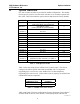
4. Option Switches
Five sets of option switches are provided for module configuration. The module
must be power cycled or reset after these switches are set so that the options will
take effect. Table 2 describes the option switches and shows the factory defaults.
SWITCH MODULE DESCRIPTION DEFAULT
GROUP unit address setting
(refer to the MCN System Manual)
00
MODULE unit address setting
(refer to the MCN System Manual)
0
OPTION A
position 1 not used
UP
position 2 not used UP
position 3 not used UP
position 4 not used UP
position 5 not used UP
position 6 not used UP
position 7 not used UP
position 8 ASTRO-TAC™ select DOWN
OPTION B
position 1 not used
UP
position 2 not used UP
position 3 synchronous clock selection, see Table 4 UP
position 4 synchronous clock selection, see Table 5 UP
SER MODE
position 1 synchronous clock selection, see Table 4
DOWN
position 2 synchronous clock selection, see Table 5 DOWN
Table 2 - AIB Option Switches
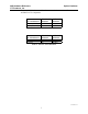
Table 3 shows the setting for the ASTRO-TAC™ select switch. This switch
configures the AIB to operate with either the ASTRO-TAC™ comparator
(supporting up to 13 receivers) or the ASTRO-TAC™ 3000 comparator
(supporting up to 64 receivers). If this switch is not set properly, the AIB will not
communicate with the comparator.
Comparator Type
Option A Switch
position 8
ASTRO-TAC™ 3000 DOWN
ASTRO-TAC™ UP
Table 3 - ASTRO-TAC Select Switch
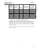
Table 4 and Table 5 show the configurations for the synchronous clock selection
switches found on the rear of the module. The default positions (internal TX