MCN Monitoring and Control Network Comparator Display System Channel Control Unit CCU-2 Hardware Reference Manual S2-61424-100 Note: Switch settings vary depending upon the system. Be sure to verify switch settings before installation Be sure to set the rotary address switches to the proper addresses before installing the system.
FCC Statement This equipment has been tested and found to comply with the limits for a Class A digital device, pursuant to Part 15 of the FCC Rules. These limits are designed to provide reasonable protection against harmful interference when the equipment is operated in a commercial environment. This equipment generates, uses, and can radiate radio frequency energy and, if not installed and used in accordance with the instruction manual, may cause harmful interference to radio communications.
CCU-2 Hardware Reference CTI Products, Inc. Standard Limited Hardware Warranty LIMITED WARRANTY. Equipment manufactured by CTI Products, Inc. is warranted to be free from defects in material and workmanship for a period of ONE (1) YEAR from date of shipment to original purchaser. Under this warranty, our obligation is limited to repairing or replacing any equipment proved to be defective by our inspection within one year of sale to the original purchaser.
CCU-2 Hardware Reference CTI Products, Inc. Manual Revisions: S2-61424-100 Original Release. CTI Products, Inc. 1211 W. Sharon Rd. Cincinnati, OH 45240 Phone: (513) 595-5900.
CCU-2 Hardware Reference CTI Products, Inc. TABLE OF CONTENTS 1. INTRODUCTION................................................................................................................7 1.1 REFERENCE DOCUMENTS ........................................................................................................7 2. SPECIFICATIONS..............................................................................................................8 3. INPUTS & OUTPUTS....................................
CCU-2 Hardware Reference CTI Products, Inc.
CCU-2 Hardware Reference CTI Products, Inc. 1. Introduction Introduction The CCU-2 Channel Control Unit is used to control functions in a Land Mobile Radio System such as: Main / Standby System Selection The CCU-2 module allows up to six independent consoles to control a common function. It allows all the consoles to force the function to Main or Standby and provides feedback to the consoles to indicate the state of the function.
CCU-2 Hardware Reference CTI Products, Inc. 2. Specifications Specifications Size 5.5” x 4.2” x 1.5” (140 x 107 x 38 mm) 19 oz (540 gm) 0 – 50 ºC 10 - 95% non-condensing +15 to +30 VDC 6 sets of Force A & Force B inputs Opto-isolated, unidirectional. External voltage required. Inactive: < 0.5 VDC across inputs Active: 5 to 30 VDC On leading edge (from Inactive to Active) A proper input transition on a Force A or Force B input will override other inputs, even those stuck active.
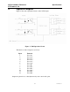
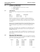
CCU-2 Hardware Reference CTI Products, Inc. 3. Specifications Inputs & Outputs Figure 2 shows the equivalent circuits of the CCU I/O pins. Figure 2 - I/O Equivalent Circuit The function of the 12 inputs is as follows: Input 1 2 3 4 5 6 7 8 9 10 11 12 Function Force A 1 Force A 2 Force A 3 Force A 4 Force A 5 Force A 6 Force B 1 Force B 2 Force B 3 Force B 4 Force B 5 Force B 6 Outputs are pinned out so that adjacent relays can control audio pairs.
CCU-2 Hardware Reference CTI Products, Inc. 4. Switches & Jumpers Theory of Operation The CCU-2 contains the following: A Single Latching Section with 8 Form C Outputs (6) Force A Inputs (6) Force B Inputs 4.1 Latch Action The latch is set to the A or B position by the Force A and Force B inputs as follows: Input Force A x Force B x Transition Inactive to Active Inactive to Active Latched State A B The CCU-2 will take action only on a transition of an input from Inactive to Active.
CCU-2 Hardware Reference CTI Products, Inc. 4.3 Switches & Jumpers LEDs The CCU-2 has input and output LEDs. Output LEDs Input LEDs A B 1 2 3 4 5 6 7 8 9 10 11 12 1 2 3 4 5 6 7 8 9 10 11 12 PWR 345 2 3456 2 45 23 6 01 EF 01 EF GROUP 01 EF DC IN ACT ERR SVC BCD OUT 78 9 6 A 4.3.1 NETWORK BCD BCD IN 78 9 A A 789 MODULE ON 1 2 3 4 OPTION RESET Input LEDs The left-side "A" LEDs are the input LEDs, one for each input.
CCU-2 Hardware Reference CTI Products, Inc. 5. Switches & Jumpers Option Switches & Jumpers Addressing and option switches are provided for module configuration. The module must be power cycled or reset after these switches are set so that the options will take effect. Press the Reset toggle switch down to reset the module. A B 1 2 3 4 5 6 7 8 9 10 11 12 1 2 3 4 5 6 7 8 9 10 11 12 PWR GROUP 345 2 3456 2 3456 2 01 EF DC IN 01 EF OUT 01 EF 5.
CCU-2 Hardware Reference CTI Products, Inc. 5.3 Switches & Jumpers Initializing the Relays The relays in the CCU-2 are magnetically latched and will retain their state when power is off. The normal state will be all On or all Off. If the relays come up in a random pattern when the power is initially applied, it is probably because the relays were jarred during transport or installation. There are two ways to initialize the relays: 1.
CCU-2 Hardware Reference CTI Products, Inc. 5.4 Switches & Jumpers Jumper Options Figure 3 shows the jumper options on the rear of the unit. E1 A E1 B CA-80024-100 Figure 3 - Jumper Options Neither of the jumper positions is connected on this unit.
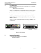
CCU-2 Hardware Reference CTI Products, Inc. 6. Connectors Connectors The NETWORK IN/OUT ports on the front of the CCU are used to connect the CCU with other MCN modules. These ports carry both the network data signals as well as DC power for power distribution with other modules. Table 5 gives the pinout for these connectors. Figure 4 shows the location of pin 1 for each port. PRODUCTS, INC.
CCU-2 Hardware Reference CTI Products, Inc. 6.1 Connectors J1 50-Pin Connector Pinout Connector J1 provides the discrete I/O signals. The following tables show the pinouts in Punch-Block order.
CCU-2 Hardware Reference CTI Products, Inc. 7. Mounting Mounting Various mounting kits are available to mount the CCU-2 module. Mounting Kits Rack Mount - 4 A size modules 1 Rack Unit (1.75") High Rack Mount - 2 A size modules plus 1 B size module 1 Rack Unit (1.75") High (Used to mount 2 CCUs and 1 EXB module.) S2-60435 S2-60443 Refer the reference 1, section Mounting Options, for physical details about mounting the CCU module.
CCU-2 Hardware Reference CTI Products, Inc. 8. Troubleshooting Operation in an MCN Network The CCU-2 module can operate in stand-alone mode with just connections to its 50 pin I/O connector and no connection to the MCN network. However, if it is used in a system with one or more PCs running MCNRCD software it may be monitored & controlled from those PCs. A special set of Default files is available for use with MCN Config configuration program for the CCU-2.
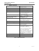
CCU-2 Hardware Reference CTI Products, Inc. 9. Troubleshooting Troubleshooting This table is a list of troubleshooting tips specific to the CCU-2 module. For additional troubleshooting tips, refer to the troubleshooting section found in the Monitoring and Control Network System Manual, reference 1. Due to the high percentage of surface-mount components, the CCU is treated as a field replaceable unit.
CCU-2 Hardware Reference CTI Products, Inc. Troubleshooting PROBLEM CAUSE The CCU doesn't hold the last state on power-up or reset Check Option Switch 4. If it is up, the CCU will initialize this state based upon Switch 3. See Table 4 – Initial State on Reset. Set Switches 3 & 4 Down and reset the unit. The CCU holds the last state on power-up (and we need it to come up in a known state) Check Option Switch 4. If it is down, the CCU will start up using the previous state.