
Manual


CCU-2 Hardware Reference Switches & Jumpers
CTI Products, Inc.
68-11843-100
10
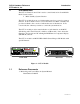
4. Theory of Operation
The CCU-2 contains the following:
A Single Latching Section with 8 Form C Outputs
(6) Force A Inputs
(6) Force B Inputs
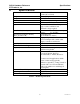
4.1 Latch Action
The latch is set to the A or B position by the Force A and Force B inputs as
follows:
Input Transition Latched State
Force A x Inactive to Active A
Force B x Inactive to Active B
The CCU-2 will take action only on a transition of an input from Inactive to
Active. If an input is stuck Active or Inactive, it will not prevent another input
from switching the state of the latch. This provides fault tolerance for stuck (or
open) inputs.
Since the relays are magnetically latched relays, they will hold their state even
when the power to the CCU-2 module is off. Upon Power-up or Reset, the CCU
will ignore the inputs for approximately 1 second to allow the inputs time to
settle.
Status bits provide feedback to PCs on the MCN network. Depending upon the
Display Table used for the particular function, the state of the output(s) and / or
the input(s) can be seen.
Control bits provide input from PCs on the MCN network. Depending upon the
Display Table used for the particular function, the operator may force the latch to
the A or B state.
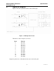
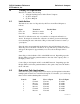
4.2 Redundant Path Applications
Since there are 6 pairs of inputs, the CCU-2 may be used in applications that have
multiple paths for the Force A and Force B signals. For instance, you could set up
three consoles with redundant paths as follows:
Console Path Force A Input Force B Input
1 Forward ForceA1 ForceB1
1 Reverse ForceA2 ForceB2
2 Forward ForceA3 ForceB3
2 Reverse ForceA4 ForceB4
3 Forward ForceA5 ForceB5
3 Reverse ForceA6 ForceB6