
Manual


CCU-2 Hardware Reference Switches & Jumpers
CTI Products, Inc.
68-11843-100
11
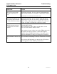
4.3 LEDs
The CCU-2 has input and output LEDs.
8
9
7
A
B
C
D
E
F
0
1
2
3
4
5
6
8
9
7
A
B
C
D
E
F
0
1
2
3
4
5
6
8
9
7
A
B
C
D
E
F
0
1
2
3
4
5
6
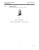
1
2
3 4
ON
PWR ACT
A
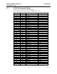
11 1210987654321
RESETDC IN OPTIONMODULEGROUP
IN
OUTNETWORK
SVC
ERR
B
1 2 3 4 5 6 7 8 9 10 11 12
4.3.1 Input LEDs
The left-side "A" LEDs are the input LEDs, one for each input.
LED On Input Active
LED Off Input Inactive
The input LED mapping is as follows:
LED Function
A1-A6 ForceA1 – Force A6
A7-A12 ForceB1 – ForceB6
The input LEDs will all blink on upon power-up as a self-test.
4.3.2 Output LEDs
Output LEDs indicate the state of each of the 8 outputs:
LED On Output A
LED Off Output B
Since all relays are driven to the same state, the output LEDs should be all on or
all off.
4.3.3 PWR, ERR, ACT LEDs
The CIB has three additional LED indicators on the front panel.
PWR On when sufficient power is present
Blinks when the voltage is low.
ERR 1 Blink: Group:Module set to FF:F (Invalid address)
2 Blinks: Improper internal daughter boards detected
Solid On: Other error (hardware or software)
ACT On: Connected to a PC running MCNRCD software
Input LEDs
Output LEDs