
Manual


CCU-2 Hardware Reference Switches & Jumpers
CTI Products, Inc.
68-11843-100
12
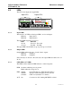
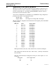
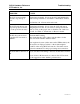
5. Option Switches & Jumpers
Addressing and option switches are provided for module configuration. The
module must be power cycled or reset after these switches are set so that the
options will take effect. Press the Reset toggle switch down to reset the module.
8
9
7
A
B
C
D
E
F
0
1
2
3
4
5
6
8
9
7
A
B
C
D
E
F
0
1
2
3
4
5
6
8
9
7
A
B
C
D
E
F
0
1
2
3
4
5
6
1
2
3 4
ON
PWR ACT
A
11 1210987654321
RESETDC IN OPTIONMODULEGROUP
IN
OUTNETWORK
SVC
ERR
B
1 2 3 4 5 6 7 8 9 10 11 12
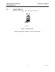
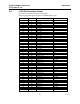
5.1 Group & Module Switches
The Group and Module rotary selector switches are used to set the node address
during module installation. Each module must have a unique Group:Module
address. Refer to the Monitor and Control Network System Manual for details
about address planning or the Custom System Configuration documentation for
pre-assigned addresses if your system is a Custom Engineered system.
SWITCH DESCRIPTION DEFAULT
GROUP unit address setting (00-FE)
refer to the MCN System Manual
00
MODULE unit address setting (0-F)
refer to the MCN System Manual
0
Table 2 – Group & Module Switches
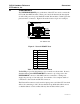
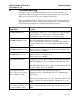
5.2 Option Switches
The Option switches allow the technician to pre-set the relay outputs.
OPTION
SWITCH
DESCRIPTION Notes Default
1 Not used Down
2 Not used Down
3 Reset Initial State See Table 4 Down
4 Reset Initialize Enable See Table 4 Down
Table 3 - Option Switches
Option Switches 3 & 4 are used to select the initial state at power-up and reset:
SW3 SW4 Initial State on Power Up or Reset Default
Down Down Do not re-initialize. Use last stored state. X
Up Down Do not re-initialize. Use last stored state.
Down Up Initialize to State B (LEDs Off)
Up Up Initialize to State A (LEDS On)
Table 4 – Initial State on Reset