
Manual


CCU-2 Hardware Reference Troubleshooting
CTI Products, Inc.
68-11843-100
18
8. Operation in an MCN Network
The CCU-2 module can operate in stand-alone mode with just connections to its
50 pin I/O connector and no connection to the MCN network. However, if it is
used in a system with one or more PCs running MCNRCD software it may be
monitored & controlled from those PCs.
A special set of Default files is available for use with MCN Config configuration
program for the CCU-2. Special items include:
Module Type: CCU-2
Display Tables CCU Input A, CCU Input B, CCU Output
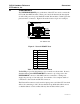
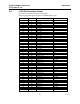
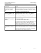
The CCU Module configuration will include the following I/O points in the MCN
Config program:
I/O Point Name Display Table
1 Force A 1 CCU Input A
2 Force A 2 CCU Input A
3 Force A 3 CCU Input A
4 Force A 4 CCU Input A
5 Force A 5 CCU Input A
6 Force A 6 CCU Input A
7 Force B 1 CCU Input B
8 Force B 2 CCU Input B
9 Force B 3 CCU Input B
10 Force B 4 CCU Input B
11 Force B 5 CCU Input B
12 Force B 6 CCU Input B
13 Output 1 CCU Output
14 Output 2 CCU Output
15 Output 3 CCU Output
16 Output 4 CCU Output
17 Output 5 CCU Output
18 Output 6 CCU Output
19 Output 7 CCU Output
20 Output 8 CCU Output
The inputs will show the state of the external Force A and Force B inputs.
The output points will show the states of the 8 relays. (All relays should show
the same state).
The state of the latch may be changed by forcing one of the outputs on or off
as follows:
MCN State CCU-2 Latch State
On A
Off B