
Manual


CCU-2 Hardware Reference Specifications
CTI Products, Inc.
68-11843-100
8
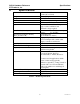
2. Specifications
Size 5.5” x 4.2” x 1.5”
(140 x 107 x 38 mm)
Weight 19 oz (540 gm)
Temperature 0 – 50 ºC
Humidity 10 - 95% non-condensing
Module Power +15 to +30 VDC
Inputs 6 sets of Force A & Force B inputs
Opto-isolated, unidirectional.
External voltage required.
Input Levels (across inputs) Inactive: < 0.5 VDC across inputs
Active: 5 to 30 VDC
Input Trigger Transition Polarity
(Force A or Force B)
On leading edge
(from Inactive to Active)
Fault Tolerance A proper input transition on a Force A
or Force B input will override other
inputs, even those stuck active.
Input Impedance: 5 K Ohms, min
Number of Sections Supported 1 Section
Outputs (for control or feedback) 8 Form C Relays, magnetically latched.
All driven in parallel
Output Contacts Bifurcated, Gold flashed
Low level (20 uA, 20 mV) to
24 VAC/VDC, 1 A Max., Resistive
Contacts used in applications which
cause contact arcing (typically
inductive, capacitive, or lamp circuits or
circuits with over 12V and 250 mA)
will not be suitable for switching low
level signals.
Maximum Power Dissipation 2 Watts
Input/Output Connection 50 pin Telco style
Network Connector (2) RJ-45 (1 in, 1 out)
Table 1 - Module Specifications