MCN Monitoring and Control Network Comparator Display System Channel Control Unit CCU Hardware Reference Manual S2-61085-105 Note: Jumpers & switch settings vary depending upon the system. Be sure to verify jumper and switch settings before installation Be sure to set the rotary address switches to the proper addresses before installing the system.
FCC Statement This equipment has been tested and found to comply with the limits for a Class A digital device, pursuant to Part 15 of the FCC Rules. These limits are designed to provide reasonable protection against harmful interference when the equipment is operated in a commercial environment. This equipment generates, uses, and can radiate radio frequency energy and, if not installed and used in accordance with the instruction manual, may cause harmful interference to radio communications.
CCU Hardware Reference CTI Products, Inc. Standard Limited Hardware Warranty LIMITED WARRANTY. Equipment manufactured by CTI Products, Inc. is warranted to be free from defects in material and workmanship for a period of ONE (1) YEAR from date of shipment to original purchaser. Under this warranty, our obligation is limited to repairing or replacing any equipment proved to be defective by our inspection within one year of sale to the original purchaser.
CCU Hardware Reference CTI Products, Inc. S2-61085-100 Manual Revisions: Original Release for CCU Version 100 (with two toggle inputs). S2-61085-105 Covers CCU Version 105 (with three sets of toggle inputs). CTI Products, Inc. 1211 W. Sharon Rd. Cincinnati, OH 45240 Phone: (513) 595-5900.
CCU Hardware Reference CTI Products, Inc. TABLE OF CONTENTS 1. INTRODUCTION................................................................................................................1 1.1 REFERENCE DOCUMENTS ........................................................................................................1 2. SPECIFICATIONS..............................................................................................................2 3. THEORY OF OPERATION ..................................
CCU Hardware Reference CTI Products, Inc.
CCU Hardware Reference CTI Products, Inc. 1. Introduction Introduction The CCU Channel Control Units are used to control functions in a Land Mobile Radio System such as: Main / Standby Base Repeat On/Off Comparator A / Comparator B Receive: Normal / Emergency Control Station (ECS) Transmit: Normal / ECS The CCU allows three independent consoles to control the above functions.
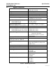
CCU Hardware Reference CTI Products, Inc. 2. Specifications Specifications Size 5.5” x 4.2” x 1.5” (140 x 107 x 38 mm) 16 oz (455 gm) 0 - 50 ºC 10 - 95% non-condensing 10 - 32 Vdc / 2 Watts max.
CCU Hardware Reference CTI Products, Inc. Specifications Figure 2 shows the equivalent circuits of the CCU I/O pins. The pull-up voltage Vp is controlled by jumper E1B, located on the rear of the module. • Vp = 15 Vdc with jumper E1B out (Default setting) • Vp = 5.0 Vdc with jumper E1B in Vp +5V 22K HCMOS IC INPUT 150K ESD PROTECTION 0.01uF 30V TRANSORB INPUT +5V Vp 180K 22K ESD PROTECTION 0.01uF 30V TRANSORB OUTPUT Vp 22K ESD PROTECTION +5V HCMOS IC INPUT 30V TRANSORB 150K 0.
CCU Hardware Reference CTI Products, Inc. 3. Theory of Operation Theory of Operation The CCU contains 5 similar toggle sections: Main / Standby Base Select Repeat On/Off Comparator A / Comparator B Select Receive: Normal / Emergency Control Station (ECS) Select Transmit: Normal / ECS Select Each section is essentially a Toggle Flip-Flop with multiple inputs and outputs.
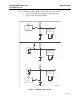
CCU Hardware Reference CTI Products, Inc. 3.2 Theory of Operation Section 1 - Main / Standby Base Selection The following logic diagram of the Main / Standby Base Select section shows the basic section logic.
CCU Hardware Reference CTI Products, Inc. 3.3 Theory of Operation Section 2 - Repeater Control The Repeater Control Section has a similar Toggle function as the Main/Standby function. There are three external inputs: • /Repeat Toggle 1 (from Console 1) • /Repeat Toggle 2 (from Console 2) • /Repeat Toggle 3 (from Console 3) There are four logic outputs: • /Repeat On 1 • /Repeat On 2 • /Repeat Off 1 • /Repeat Off 2 3.3.
CCU Hardware Reference CTI Products, Inc. 3.4 Theory of Operation Section 3 – Comparator A/B Select The Comparator A/B Select section has a similar Toggle function as the Main/Standby function.
CCU Hardware Reference CTI Products, Inc. 3.6 Theory of Operation Section 5 – TX Normal / ECS Select The Tx Normal / ECS Select section has a similar Toggle function as the Main/Standby function.
CCU Hardware Reference CTI Products, Inc. 4. Switches & Jumpers Option Switches & Jumpers Three sets of option switches are provided for module configuration. The module must be power cycled or reset after these switches are set so that the options will take effect. 4.1 Group & Module Switches The Group and Module selector switches are used to set the node address during module installation. Refer to the Monitor and Control Network System Manual for details about setting these switches.
CCU Hardware Reference CTI Products, Inc. 4.3 Switches & Jumpers Jumper Options Figure 4 shows the configuration of the two jumper options available on the rear of the CCU. These jumpers should be installed at system installation time with power removed from the CCU. E1 A E1 B CA-80024-100 Figure 4 - Jumper Options Jumper E1A is located across the top 2 terminals of the 6 pin terminal block. Jumper E1B is located across the left side middle and bottom terminals of the 6 pin terminal block.
CCU Hardware Reference CTI Products, Inc. 5. Connectors Connectors The NETWORK IN/OUT ports on the front of the CCU are used to connect the CCU with other MCN modules. These ports carry both the network data signals as well as DC power for power distribution with other modules. Table 7 gives the pinout for these connectors. Figure 5 shows the location of pin 1 for each port. PRODUCTS, INC.
CCU Hardware Reference CTI Products, Inc. Connectors Table 8 - CCU Connector J1 Pinout in Logical Order CCU J1 HW Pin I/O CIB Funct. CCU Sect.
CCU Hardware Reference CTI Products, Inc. Connectors Table 9 - CCU Connector J1 Pinout in Punch Block Order CCU J1 26 1 27 2 28 3 29 4 30 5 31 6 32 7 33 8 34 9 35 10 36 11 37 12 38 13 39 14 40 15 41 16 42 17 43 18 44 19 45 20 46 21 47 22 48 23 49 24 50 25 HW I/O O Gnd I/O I/O I/O I/O I I I/O I/O O O I/O I/O I/O I/O I I I/O I/O O O I/O I/O I/O I/O I I I/O I/O O O O I/O I/O I/O I/O I I I/O I/O CIB Funct.
CCU Hardware Reference CTI Products, Inc. 6. Mounting Mounting Various mounting kits are available to mount the CCU module. Mounting Kits Rack Mount - 4 A size modules 1 Rack Unit (1.75") High Rack Mount - 2 A size modules plus 1 B size module 1 Rack Unit (1.75") High (Used to mount 2 CCUs and 1 EXB module.) S2-60435 S2-60443 Refer the reference 1, section Mounting Options, for physical details about mounting the CCU module.
CCU Hardware Reference CTI Products, Inc. 7. Troubleshooting Operation in an MCN Network The CCU can be seen in an MCN network as a CIB unit or as a CCU unit. If the MCNRCD software is configured to see it as a CIB unit, only the first 5 (toggle) sections will be active as Function Blocks. For each function block (section) of the CCU, you will have to select an appropriate Display Table to use. Standard CCU Display Tables are: Section 1 2 3 4 5 Type Main/Standby Base Repeater On/.
CCU Hardware Reference CTI Products, Inc. 8. Troubleshooting Troubleshooting This table is a list of troubleshooting tips specific to the CCU module. For additional troubleshooting tips, refer to the troubleshooting section found in the Monitoring and Control Network System Manual, reference 1. Due to the high percentage of surface-mount components, the CCU is treated as a field replaceable unit.
CCU Hardware Reference CTI Products, Inc. Troubleshooting The standard CIB-T Switch & LED Test Board may be used to test the functionality of the CCU module. Switch and LED assignments appear below.