
User guide

CCU Hardware Reference Switches & Jumpers
CTI Products, Inc.
68-11843-105
9
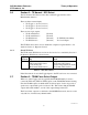
4. Option Switches & Jumpers
Three sets of option switches are provided for module configuration. The module
must be power cycled or reset after these switches are set so that the options will
take effect.
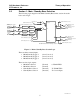
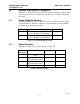
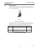
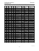
4.1 Group & Module Switches
The Group and Module selector switches are used to set the node address during
module installation. Refer to the Monitor and Control Network System Manual
for details about setting these switches.
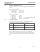
SWITCH DESCRIPTION DEFAULT
GROUP unit address setting (00-FE)
refer to the MCN System Manual
00
MODULE unit address setting (0-F)
refer to the MCN System Manual
0
Table 4 – Group & Module Switches
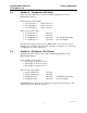
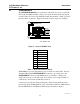
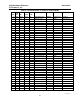
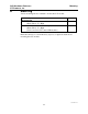
4.2 Option Switches
The Option switches control special functions of the CCU.
OPTION
SWITCH
DESCRIPTION Up Down
1 TX Normal / ECS Slave
Mode
Slaved to RX Independent
2 Force Repeat Disable
when Rx ECS selected
Forced Normal
3 Force Repeat Disable
when Tx ECS selected
Forced Normal
4 not used
Table 5 - Option Switches