MCN Monitoring and Control Network GPIO General Purpose Input/Output Module Hardware Reference Manual S2-61286-100 Note: Switch settings vary depending upon the system. Be sure to verify switch settings before installation Be sure to set the rotary address switches to the proper addresses before installing the system.
FCC Statement This equipment has been tested and found to comply with the limits for a Class A digital device, pursuant to Part 15 of the FCC Rules. These limits are designed to provide reasonable protection against harmful interference when the equipment is operated in a commercial environment. This equipment generates, uses, and can radiate radio frequency energy and, if not installed and used in accordance with the instruction manual, may cause harmful interference to radio communications.
GPIO Hardware Reference CTI Products, Inc. Standard Limited Hardware Warranty LIMITED WARRANTY. Equipment manufactured by CTI Products, Inc. is warranted to be free from defects in material and workmanship for a period of ONE (1) YEAR from date of shipment to original purchaser. Under this warranty, our obligation is limited to repairing or replacing any equipment proved to be defective by our inspection within one year of sale to the original purchaser.
GPIO Hardware Reference CTI Products, Inc. Manual Revisions: S2-61286-100 Original Release.
GPIO Hardware Reference CTI Products, Inc. TABLE OF CONTENTS 1. INTRODUCTION......................................................................................................................7 1.1 MODELS ......................................................................................................................................7 1.2 MODULE USAGE IN A SYSTEM.....................................................................................................8 1.3 REFERENCE DOCUMENTS ..............
GPIO Hardware Reference CTI Products, Inc.
GPIO Hardware Reference CTI Products, Inc. Introduction 1. Introduction The General Purpose Input/Output Modules are part of CTI Products’ MCN™ Monitoring and Control Network. Versions are available with combinations of opto-isolated inputs, SSR (Solid-State Relay) outputs, or mechanical relay outputs.
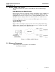
GPIO Hardware Reference CTI Products, Inc. Introduction 1.2 Module Usage in a System This section describes the operation of the GPIO module in an MCN display system. Input Monitoring and Output Control Off/on status from devices connected to inputs of the GPIO is sent to a MCN User Interface Module over the MCN network. The User Interface Module (such as the HIB-IP) then transfers the status to the PC running MCNRCD Software. The MCNRCD Software displays the device status information on the PC monitor.
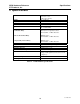
GPIO Hardware Reference CTI Products, Inc. Specifications 2. Specifications MCN Size A 5.5” x 4.2” x 1.5” (140 x 107 x 38 mm) 19 oz (540 gm) 0 – 50 ºC 10 - 95% non-condensing +15 to +30 VDC Optically Isolated 12 – 24 VAC/VDC Size Weight Temperature Humidity Module Power Inputs Output Options Solid State Relay SPST (Form A) Optically Isolated 24 VAC/VDC, 1 A Max. Resistive Electro-Mechanical Relay SPDT (Form C) 48 VAC/VDC, 1 A Max.
GPIO Hardware Reference CTI Products, Inc. Inputs & Outputs 3. Inputs & Outputs Figure 3 shows the equivalent input and output circuits of the GPIO.
GPIO Hardware Reference CTI Products, Inc. Inputs & Outputs 3.1 Solid State Relay Option The default setting for Solid State Relay output current is 1 A maximum, resistive. For this setting, the relay on-resistance is 500 m-ohms. For DC loads only, an internal jumper setting is available to allow 1.5 A maximum, with an onresistance of 150 m-ohms. The maximum current stated above is for resistive loads only. For inductive loads, the maximum current must be de-rated.
GPIO Hardware Reference CTI Products, Inc. Indicators 4. Indicators 4.1 Input and Output LEDs The GPIO has LEDs to display the status of all installed inputs and outputs. Status LEDs for inputs are green. Status LEDs for outputs are red. The following shows a GPIO module configured with 12 inputs (on the left) and eight outputs (on the right). LEDs will be lit when the input or output is active.
GPIO Hardware Reference CTI Products, Inc. Option Switches & Jumpers 5. Option Switches & Jumpers Addressing and option switches are provided for module configuration. The module must be power cycled or reset after these switches are set so that the options will take effect. Press the Reset toggle switch down to reset the module. 5.1 Group & Module Switches The Group and Module rotary selector switches are used to set the node address during module installation.
GPIO Hardware Reference CTI Products, Inc. 5.2.1 Option Switches & Jumpers Initializing the Relays Magnetically-Latched relays in the GPIO will retain their state when power is off. The initial state of relays after power-up will be all ON or all OFF. If the relays come up in a random pattern when the power is initially applied, it is probably because the relays were jarred during transport or installation. To initialize the relays to the ON state: 1. Set switches as follows: 3 Up 4 Up. 2.
GPIO Hardware Reference CTI Products, Inc. Option Switches & Jumpers 5.3 Jumper Options Figure 5 shows the jumper options on the rear of the unit. Note that neither of these jumpers is connected internally on the GPIO, and therefore, has no usage.
GPIO Hardware Reference CTI Products, Inc. Connectors 6. Connectors 6.1 Network Connectors The NETWORK IN/OUT ports on the front of the GPIO are used to connect the GPIO with other MCN modules. These ports carry both the network data signals as well as DC power for power distribution with other modules. Table 7 gives the pinout for these connectors. Figure 6 shows the location of pin 1 for each port. PRODUCTS, INC.
GPIO Hardware Reference CTI Products, Inc. Connectors 6.3 J1 50-Pin Connector Pinout Connector J1 provides access to the discrete I/O signals. The following tables show the connector pinout in Punch-Block order. An I/O option (such as 12I, 12O, 8C, or 8L) can be installed in either the ‘A’ Option Position of the GPIO module, or the ‘B’ Option Position, or both.
GPIO Hardware Reference CTI Products, Inc. 6.3.
GPIO Hardware Reference CTI Products, Inc. 6.3.
GPIO Hardware Reference CTI Products, Inc. 6.3.
GPIO Hardware Reference CTI Products, Inc. 6.3.
GPIO Hardware Reference CTI Products, Inc. Mounting 7. Mounting Various mounting kits are available to mount the GPIO module. Mounting Kits Rack Mount - 4 A size modules 1 Rack Unit (1.75") High Rack Mount - 2 A size modules plus 1 B size module 1 Rack Unit (1.75") High (Used to mount 2 GPIOs and 1 EXB module.) S2-60435 S2-60443 Refer to Monitoring and Control Network System Manual S2-60425, Mounting Options section, for physical details about mounting the GPIO module.
GPIO Hardware Reference CTI Products, Inc. Troubleshooting 8. Troubleshooting This table is a list of troubleshooting tips specific to the GPIO module. For additional troubleshooting tips, refer to the troubleshooting section found in the Monitoring and Control Network System Manual S2-60425. Due to the high percentage of surface-mount components, the GPIO is treated as a field replaceable unit.
GPIO Hardware Reference CTI Products, Inc. Troubleshooting PROBLEM CAUSE The last state of MagneticallyLatched relays is not held on power-up or reset Check Option Switch 4. If it is up, the GPIO will initialize this state based upon Switch 3. See Table 6 – Initial State on Reset. Set Switches 3 & 4 Down and reset the unit. The last state of MagneticallyLatched relays is held on power-up, but a known state is required Check Option Switch 4.