
Manual


HIB Hardware Reference Option Switches
CTI Products, Inc.
68-10855-210
4
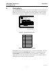
4. Option Switches
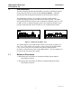
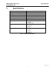
Five sets of option switches are provided for module configuration. The module
must be power cycled or reset after these switches are set so that the options will
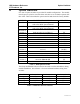
take effect. Table 2 describes the option switches and shows the factory defaults.
SWITCH MODULE DESCRIPTION DEFAULT
GROUP unit address setting
refer to the MCN System Manual
00
MODULE unit address setting
refer to the MCN System Manual
0
OPTION A
position 1 baud rate select 0 (see Table 3) UP
position 2 baud rate select 1 (see Table 3) DOWN
position 3 baud rate select 2 (see Table 3) UP
position 4 reserved DOWN
position 5 HIB mode select DOWN
position 6 reserved DOWN
position 7 reserved DOWN
position 8 reserved DOWN
OPTION B
position 1 reserved DOWN
position 2 reserved DOWN
position 3 reversed DOWN
position 4
reserved--Must be Down
DOWN
SER MODE
position 1
reserved-- Must be UP
UP
position 2
reserved-- Must be UP
UP
Table 2 - HIB Option Switches
The Group and Module selector switches are used to set the unit address during
module installation. See reference 1 for more information about setting these
switches.
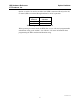
Baud Rate baud rate select 0 baud rate select 1 baud rate select 2
9600 bps UP UP DOWN
14400 bps DOWN DOWN DOWN
19200 bps DOWN DOWN UP
38400 bps UP DOWN UP
Table 3 - Baud Rate Selector Switches