
Manual


CTI Products, Inc. HIB-IP & HIB-IP 8000 Hardware Reference Manual
Appendix B. Mounting Options 22
Wall Mount Option
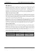
The wall mount option allows an HIB-IP module to be mounted to any flat surface. The HIB-IP module has
four screw holes on the bottom. Simply attach the two mounting plates to the bottom of the module using the
four flat-head screws provided with the wall mount kit. This assembly is then attached to the flat surface with
user-provided fasteners. Figure 6 shows a dimensioned view of the wall mount installation.
Industry
Canada
NOTE:
THE NUMBERS ON THIS DRAWING REFER TO THE ITEM NUMBERS
ON THE CORRESPONDING BILLS OF MATERIAL FOR THIS ASSEMBLY.
24 VDC
100 mA
BOTTOM VIEW
USE ONLY 6-32 X 1/4" LONG
FLAT HEAD SCREWS TO ATTACH THE
WALL MOUNT BRACKET TO THIS UNIT.
TO PREVENT DAMAGE TO THE CIRCUIT BOARD.
CAUTION!
USE ONLY 6-32 X 1/4" LONG
FLAT HEAD SCREWS TO ATTACH THE
WALL MOUNT BRACKET TO THIS UNIT.
TO PREVENT DAMAGE TO THE CIRCUIT BOARD.
CAUTION!
ETL APPRO
3.500
1.980
6.130
6.700
1.642
TOP VIEW
1
2
Provided by installer.
Allow room on ends
for connectors.
Allow room on ends
for connectors.
SIDE VIEW
1.980
QTY 2
QTY 4
QTY 4 NO. 8 SCREWS OR OTHER
APPROPRIATE HARDWARE.
OR
OR
1
2
3
4
5
6
7
8
ON
OPTION A
DC IN
ERR
ACT
PWR
RSVC
CSVC
AUDIO
LINE
CD
OH
RESET
CMD
NCB
NETWORK COMBINER
NETWORK
Figure 6 HIB-IP Module Wall Mounting
CAUTION
Be sure to use the flat head screws provided with the wall mount kit. If you are not using the wall mount
kit from CTI Products, Inc., make sure that the screws do not protrude into the enclosure more than 0.125
inches from the bottom surface of the module.
Using a longer screw that touches the PC board inside the module may damage the module. Doing so will
void the unit’s warranty.