Monitoring and Control Network (MCN™) Comparator Display System System Planner S2-60616-100 August, 1996 68-11135-100
Disclaimer Note The information within this document has been checked and is believed to be reliable. However, no responsibility is assumed for any inaccuracies. Furthermore, CTI Products, Inc. reserves the right to make changes to any products herein to improve reliability, function, or design. CTI Products, Inc. assumes any liability arising out of the application or use of any product, recommendation or circuit described herein: neither does it convey any license under their patents or right of others.
Table of Contents 1. INTRODUCTION AND MANUAL OVERVIEW.......................................................................................................1 1.1 MCN SYSTEM OVERVIEW ...............................................................................................................................................2 2. SYSTEM OPERATION.................................................................................................................................................3 2.
Table of Contents 6. APPENDIX B AVAILABLE DOCUMENTS............................................................................................................ 33 7. APPENDIX C SYSTEM EXAMPLES....................................................................................................................... 34 7.1 EXAMPLE 1 - PC BASED SYSTEM FOR DIGITAC COMPARATOR-- 8 RECEIVERS.......................................................... 34 7.
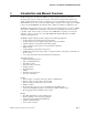
Section 1. Introduction and Manual Overview 1. Introduction and Manual Overview The Monitoring and Control Network (MCN™) Comparator Display system provides remote monitoring and control for voting receiver systems. It extends the comparator status indicators for display on a PC and allows an operator or technician to force-vote and disable receivers from a PC. With the MCN system you can control and display multiple comparators from a single point or multiple points.
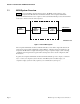
Section 1. Introduction and Manual Overview 1.1 MCN System Overview Figure 1 shows a basic MCN comparator display system. The MCN system is made up of two modules, a Comparator I/O Module and a User Interface Module. The Comparator I/O Module provides the hardware interface to the comparator. The User Interface Module provides the mechanism for the user to monitor and control the comparator.
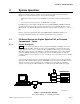
Section 2. System Operation 2. System Operation This section describes the basic operation of both Comparator I/O Modules and User Interface Modules in a comparator display system. Two systems are described: • A PC based system connected to three DIGITAC, Spectra-TAC, or Ericsson / GE comparators, and • A console-based system connected to an ASTRO-TAC comparator.
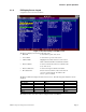
Section 2. System Operation 2.1.2 MCN Remote Comparator Display PC Software Operation Two programs make up the MCN RCD software package. They are: • MCNCFG.EXE - the configuration program • MCNRCD.EXE - the runtime Remote Comparator Display program. The MCNCFG program is run by an engineer or technician to build the configuration files when the system is installed or changed. The MCN RCD program is run by a dispatcher or technician to display the status of the voting system.
Section 2. System Operation 2.1.
Section 2. System Operation 2.1.5 Controlling Receivers You can use the MCN RCD program to control the receiver operation at your remote comparator. You can manually FORCE VOTE a receiver from the PC and listen to its audio quality over your system. You can also DISABLE a receiver that is defective or has a bad phone line. When the receiver or phone line is repaired, you can re-enable the receiver from the PC. Receivers can be controlled with either the mouse or keyboard. 2.1.
Section 2. System Operation 2.2 Console-Based System with ASTRO-TAC Comparator 2.2.1 System Description The following diagram shows a simple system for ASTRO-TAC comparator display and control on a console. The AIB ASTRO-TAC Interface Module is connected to the comparator via a serial cable. The IIB I/O Interface Module is connected to 16-I/O boards in a Central Electronics Bank (CEB).
Section 2. System Operation 2.2.2 IIB Module Connections to a Console In a console-based system, the VOTE and DISABLE control lines that connect to the I/O lines of the console are actually bi-directional signals. Figure 5 shows the interface between the console electronics and the IIB’s J1 connector.
Section 3 System Components and Specifications 3. System Components and Specifications 3.1 Module Types The MCN Module types consist of five classes or types of modules: • Comparator Input/Output Modules • User Interface Modules. • Transmitter Steering Interface Modules • System Extender Modules • Router and Repeater Modules 3.1.1 Comparator Input Output Modules (CIBs and AIBs) Comparator I/O Modules provide the physical connection between the comparator and the MCN network.
Section 3 System Components and Specifications 3.1.3 Transmitter Steering Interface Modules (TIBs) The Transmitter Steering Interface Modules (TIBs) work in conjunction with the CIB comparator Interface Modules and external Transmitter Steering equipment, such as the TSAM Transmitter Steering Unit from CTI Products. This interface provides monitor and control of transmitter sites from a PC with a HIB as the Operator Interface Module.
Section 3 System Components and Specifications 3.2 Common Specifications for Modules All modules are housed in similar metal enclosures. They all have similar environmental and power requirements. The common specifications are listed in Table 1. Specifications for features specific to a module or specifications that differ from these common specifications are listed in that module’s section of this manual. Size 5.5” x 4.2” x 1.
Section 3 System Components and Specifications 3.4 Comparator Interface Module (CIB) The CIB connects various types of comparators with parallel I/O facilities to the MCN network. Features of the CIB module include: • Parallel bi-directional I/O line connections between the CIB and a parallel I/O comparator, including Motorola DIGITAC, Spectra TAC, TAC, and Ericsson / GE analog comparators. • Support for up to 8 receivers per module.
Section 3 System Components and Specifications • FORCE VOTE and DISABLE switch functions are controlled with either a mouse or keyboard. • Allows logging (to the screen and/or to a disk file) of receivers that fail or become disabled. Logging may be enabled or disabled by the operator. • Modem support allows remote monitoring and control.
Section 3 System Components and Specifications 3.7 Transmitter Steering Interface Module (TIB) The Transmitter Steering Interface Modules (TIBs) work in conjunction with the CIB comparator Interface Modules and external Transmitter Steering equipment, such as the TSAM Transmitter Steering Unit from CTI Products.
Section 3 System Components and Specifications 3.8 EXB System Extender Module The EXB modules are used in pairs to connect two MCN networks together or to extend the length of an MCN network beyond 4000 feet. One side of each EXB module connects to the MCN network. The other side connects to a 2-wire or 4-wire leased telephone line or analog microwave channel.
Section 4. System Installation Options 4. System Installation Options 4.1 Mounting Options EIA 19” rack mount, DIGITAC bracket and cable rear mount, and Wall mount kits are available for MCN modules. These kits are described below. 4.1.1 Rack Mounting The quad rack mount option provides a 19” rack mounting bracket that supports four MCN size A modules. It requires 1 Rack Unit (1.75”) of rack space.
Section 4. System Installation Options 4.1.2 DIGITAC Bracket and Cable Rear Mount The DIGITAC rear mount bracket and cable provides a quick and easy way to mount the CIB and connect it to the DIGITAC without extra cables and punch blocks. The CIB module I/O connector has a pinout that matches the DIGITAC P805 connector. The rear mount includes a ribbon “T” connector.
Section 4. System Installation Options 4.1.3 Wall Mounting The wall mount option allows a module to be mounted to a flat surface. Each MCN module has two screw holes located on the bottom of the module. Simply attach the mounting plate to the bottom of the module using these two screw holes and then screw this assembly to the wall. The module can be mounted in any orientation. Figure 9 shows an exploded view of the wall mount installation. PRODUCTS, INC.
Section 4. System Installation Options 4.2.3 Spectra-TAC and TAC Comparators and Ericsson Analog Voters There are 3 general ways to connect to these types of comparators: 4.2.4 1. Male to male 25-pair cable to punch block with field wiring to back of comparator. This option provides the most flexibility, but it requires a punch block and a place to mount it. 2. Male to blunt end 25-pair cable wired directly to the back of the comparator card cage.
Section 4. System Installation Options One side of the network cable is shown below. This diagram details the pinout and twisted pair configuration of the cable. 1 2 3 4 5 6 7 8 TOP VIEW OF CONNECTOR DATA + DATA +POWER NC NC -POWER -POWER +POWER CA-80042-100 Figure 10 - MCN Cable Pinout When cabling your system, daisy-chain the modules together and insert a network terminator into the unused port of the first module and the unused port of the last module in the chain.
Section 4. System Installation Options 4.4 Power Requirements / Power Supply Specifications Power input for all MCN modules is 10 to 32 VDC, with most modules requiring 2 W nominal. AC power supplies are available that provide 18 VDC at 800 mA. MCN systems have been fully tested for appropriate immunity to harmful electrical noise and electrical impulses when assembled with these power supplies.
Section 4. System Installation Options In the example shown in Figure 13, two power supplies are required, even though there are only four modules in the system. The second supply is required because the network cable between the third and fourth modules is greater than the 100 foot cable length maximum for power distribution.
Section 5 Designing and Ordering a System 5. Designing and Ordering a System The following procedures should be followed when designing and ordering an MCN system. Step 1 2 3 4 5 6 Operation Determine the type of comparator in the system: Spectra-TAC, DIGITAC TAC, or ASTRO-TAC comparator or Ericsson / GE analog voters. Determine the total quantity of comparators in the system. Determine how many receivers are connected to each comparator.
Designing an MCN system 5.1 Designing an MCN system Before designing an MCN system, follow steps 1-6 on page 23. 5.1.1 Network Planning / Equipment Location Typically, comparator interfaces (CIBs and AIBs) will be mounted near the comparators, either in rack mounts or in DIGITAC Bracket and Cable Rear Mount. For DIGITAC comparators, the DIGITAC Rear Mount is the preferred method to mount the CIB because it includes a ribbon cable for quick and easy connection. It also conserves rack space.
Designing an MCN system Can you connect multiple channels (card cages) to a single CIB to save cost? Yes, so long as you are connecting only one type of comparator to one CIB. For example, in a system that had 6 Spectra-TAC channels each with only 4 receivers, one CIB could be connected to 2 channels, and only 3 CIBs would be required, but there would be no pre-wired expansion.
Designing an MCN system 5.2 MCN System Components Below is a list of MCN modules and accessories available to build your comparator display system. CTI Products PART NUMBER COMPONENT Comparator I/O Modules Comparator Interface Module (CIB) For DIGITAC, Spectra-TAC and other parallel I/O comparators.
Designing an MCN system Custom Length Network Cables Cable Assy Network Base Order 1 base and X feet of one of the following: Cable Network Custom Length (per foot) Cable Network Custom Length Plenum (per foot) Power Supplies 120 VAC U.S.
Designing an MCN system 5.3 Custom System Configuration Worksheet Step Operation 1 Determine the number of networks required. With PC Display, typically only 1 network will be used, so that the PC can see all the comparators. If you are using ASTRO-TAC comparators and Logic I/O (AIBs and IIBs) exclusively, they can be configured as multiple stand-alone networks. Contact a systems engineer from CTI Products, Inc. at (513) 595-5900 if you have any of the following systems: Remotely located (> 4000 ft.
Designing an MCN system 5 Check for maximum number of comparator modules: Calculate the total number of required comparator modules: AIB Modules from Step 2 CIB Modules from Step 4 Total _________ _________ _________ (Maximum 20) 6 If you need more than 20 CIBs and AIBs on one network, call a system engineer at CTI Products, Inc. Order the number of Local PC User Interfaces required. Local PCs are connected to the MCN network (maximum 4000’ total).
Designing an MCN system 9 Calculate the number of mounts required for Extended IIBs (IIBs mounted near the CEB but not in the same rack as the comparator interfaces.
Designing an MCN system 13 a Order Punch Blocks Total 25-pair cables connected to Punch Blocks (from above): Divide the total of 25-pair cables by 2 and round up to the next whole number. Order the proper quantity of punch blocks.
Designing an MCN system 17 a b Total number of modules: (CIBs, AIBs, IIBs, HIBs) Divide by 4 and round up to next whole number This is the basic number of power supplies needed.
Appendix B Available Documents 6.
Appendix C System Examples 7. Appendix C System Examples The following examples show how MCN modules are combined to form various systems, as well as the capabilities of those systems. 7.1 Example 1 - PC Based System for DIGITAC Comparator-- 8 Receivers Figure 14 shows a system that provides local monitoring and control of up to 8 receivers utilizing a PC as the operator interface.
Appendix C System Examples 7.2 Example 2 - PC Based dial-up System for Spectra-TAC or Ericsson Comparator-- 12 Receivers Figure 15 shows a simple dial-up system to monitor and control 12 or 16 receivers. This system assumes the following: • Spectra-TAC or Ericsson / GE Comparator, 16 (or 12) Receivers maximum, • Dial-Up PC Display • CIBs & HIB will be rack mounted • Wiring will be directly to the back of the comparator backplanes with no punch blocks.
Appendix C System Examples 7.3 Example 3 - Extended Distance Spectra-TAC or Ericsson Comparator Connected to a Console -- 16 Receivers A multiple comparator system is shown in Figure 17. This system implements monitoring and control of 3 different comparators from one console.
Appendix C System Examples Equipment List for Example System 3 Item 1 2 3 Model/Option S2-60433 S2-60442 S2-60435 4 89-10837 5 31-10354 6 7 8 9 S2-60438 S2-60536 S2-60318 81-10398 Description IIB Input/Output Interface Module CIB Comparator Interface Module Quad Rack Mount Size A (1) for CIBs, (1) for extended IIBs Cable Assy 25 pr M-M 25' (2) for CIBs, (2) for IIBs Punch Block, 50-Pair (1) for CIBs, (1) for IIBs Cable Assy Network 9" 400 Ft Network Cable Network Terminator Power Supply N.
Appendix C System Examples 7.4 Example 4 - 24 Receivers with Multiple Operator Positions The example in Figure 17 shows a much larger system than the previous examples. Three CIB modules are used to control a total of 24 receivers. The three IIB modules can be used to provide control of all receivers from the main console. Each PC in the system can control all receivers as well. The HIB modules provide both local and remote control of all receivers.
Appendix C System Examples This system allows parallel status and control of three comparators from three operator locations. If an operator at one location force votes a receiver, the other two operator stations will show that receiver as voted. Or, if an operator disables a receiver, all other operator stations will also show that receiver as disabled. If one of the comparators signals that a receiver is voted, all three stations will show the receiver being voted.
Appendix C System Examples 7.5 Example 5 - ASTRO-TAC Comparator with 8 Receivers Displayed on a Console Figure 18 shows an MCN system that provides monitoring and control of up to 8 receivers connected to a Motorola ASTRO-TAC comparator. Since the system has only 8 receivers, only one IIB module is required.
Appendix C System Examples 7.6 Example 6 - Multiple Remote PCs using EXB System Extenders When only one remote PC is needed to monitor remote comparators, a HIB Host Computer Interface Module and a pair of modems are used. If multiple PCs are required, that method would require multiple telephone lines, one for each PC. Figure 19 shows a way to connect multiple PCs to remote comparators using only one phone line.
Appendix C System Examples 7.7 Example 7 - Multi-Site Comparator Networks Zone & Master/Slave (Sub) Comparators Many voting systems covering a large geographic area will have comparators located at multiple sites. In this way, comparators for particular zones are located close to their receivers, with the voted audio brought back to the dispatch center on a single phone line for each zone. This greatly reduces the length and cost of the associated telephone lines.
Appendix C System Examples 7.8 Example 8 - Controlling Transmitter Steering Systems using TIB Modules Figure 21 shows a single-channel 8-receiver comparator system, a TSAM Transmitter Steering Unit, and a TIB Transmitter Steering Interface Module. Systems using TIB Transmitter Steering Interface Modules and TSAM Transmitter Steering Units are considered custom designed systems. Please contact a CTI Products application engineer for help in designing a system.
Appendix D Module Addressing and Receiver Banks 8. Appendix D Module Addressing and Receiver Banks 8.1 Module Addressing Each MCN module is identified by a unique address that must be set at installation time. This address is specified by the combination of a Group number and a Module number. The Group and Module numbers are assigned with the rotary switches on either the front or back of the module.
Appendix D Module Addressing and Receiver Banks 8.2 Receiver Banks The CIB parallel Comparator Interface Module controls and monitors 8 receivers. The AIB supports all 16 receivers of an ASTRO-TAC comparator. For Comparator I/O Modules such as the AIB module that support more than 8 receivers, the receivers are grouped into banks of 8 receivers. Some User Interface Modules, such as HIBs operating with the MCN Remote Comparator Display software support only bank 0.
Appendix E System Limitations when using HIB and IIB Modules Together 9. Appendix E System Limitations when using HIB and IIB Modules Together Because the console VOTE and DISABLE lines are bi-directional, the console’s LEDs will be lit if the console’s outputs are active. Because of this, the console could still indicate a DISABLE or VOTE on a receiver even if there is a problem in the network cabling or the Comparator I/O Module. Take for example the system shown in Figure 4.
Appendix F Warranty 10. Appendix F Warranty Standard Limited Hardware Warranty LIMITED WARRANTY. Equipment manufactured by CTI Products, Inc. is warranted to be free from defects in material and workmanship for a period of ONE (1) YEAR from date of installation, up to a maximum of 14 months from shipment from CTI Products, Inc. Under this warranty, our obligation is limited to repairing or replacing any equipment proved to be defective by our inspection within one year of sale to the original purchaser.
Appendix G Customer Support 11. Appendix G Customer Support For Pre- and Post-sale support, large systems, custom system design, or special applications contact: CTI Products, Inc. 1211 West Sharon Road Cincinnati, Oh 45240 Phone: (513) 595-5900 Fax: (513)595-5983.
Appendix H Glossary 12. Appendix H Glossary 16 I/O Module This is a generic term for the B1426 Comparator Interface Module in the CEB of a Centracom Series II console. AIB Module ASTRO-TAC Comparator Interface Module. The AIB Module connects Motorola’s ASTRO-TAC comparator to the MCN network. CEB Central Electronics Bank for a Centracom Series II (or later) console. CIB Module Comparator Interface Module.