
Owner manual

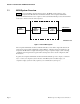
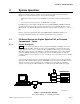
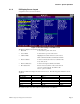
Table of Contents
MCN Comparator Display System Planner Page i
1.
INTRODUCTION AND MANUAL OVERVIEW.......................................................................................................1
1.1 MCN S
YSTEM
O
VERVIEW
...............................................................................................................................................2
2.
SYSTEM OPERATION.................................................................................................................................................3
2.1 PC-B
ASED
S
YSTEM FOR
D
IGITAC
, S
PECTRA
-TAC,
OR
E
RICSSON
C
OMPARATORS
/ V
OTERS
...........................................3
2.1.1 System Description...................................................................................................................................................3
2.1.2 MCN Remote Comparator Display PC Software Operation....................................................................................4
2.1.3 System Hardware Requirements ..............................................................................................................................4
2.1.4 PC Display Screen Layout.......................................................................................................................................5
2.1.5 Controlling Receivers ..............................................................................................................................................6
2.1.6 Error Logging ..........................................................................................................................................................6
2.1.7 MCN RCD Software Configuration .........................................................................................................................6
2.2 C
ONSOLE
-B
ASED
S
YSTEM WITH
ASTRO-TAC C
OMPARATOR
........................................................................................7
2.2.1 System Description...................................................................................................................................................7
2.2.2 IIB Module Connections to a Console.....................................................................................................................8
3.
SYSTEM COMPONENTS AND SPECIFICATIONS................................................................................................9
3.1 M
ODULE
T
YPES
...............................................................................................................................................................9
3.1.1 Comparator Input Output Modules (CIBs and AIBs) ..............................................................................................9
3.1.2 User Interface Modules (HIBs and IIBs) .................................................................................................................9
3.1.3 Transmitter Steering Interface Modules (TIBs) .....................................................................................................10
3.1.4 System Extension Modules (EXBs).........................................................................................................................10
3.1.5 Router and Repeater Modules................................................................................................................................10
3.2 C
OMMON
S
PECIFICATIONS FOR
M
ODULES
.....................................................................................................................11
3.3 ASTRO-TAC C
OMPARATOR
I
NTERFACE
M
ODULE
(AIB).............................................................................................11
3.4 C
OMPARATOR
I
NTERFACE
M
ODULE
(CIB) ....................................................................................................................12
3.5 H
OST
C
OMPUTER
I
NTERFACE
M
ODULE
(HIB)
AND
MCN RCD S
OFTWARE
..................................................................12
3.6 I
NPUT
/O
UTPUT
I
NTERFACE
M
ODULE
(IIB) ....................................................................................................................13
3.7 T
RANSMITTER
S
TEERING
I
NTERFACE
M
ODULE
(TIB)....................................................................................................14
3.8 EXB S
YSTEM
E
XTENDER
M
ODULE
...............................................................................................................................15
4.
SYSTEM INSTALLATION OPTIONS......................................................................................................................16
4.1 M
OUNTING
O
PTIONS
......................................................................................................................................................16
4.1.1 Rack Mounting.......................................................................................................................................................16
4.1.2 DIGITAC Bracket and Cable Rear Mount.............................................................................................................17
4.1.3 Wall Mounting .......................................................................................................................................................18
4.2 P
ARALLEL
I/O C
ABLING
.................................................................................................................................................18
4.2.1 DIGITAC Comparators Cabling with DIGITAC Bracket and Cabling .................................................................18
4.2.2 DIGITAC Comparators Cabling with DIGITAC Rack or Wall Mount..................................................................18
4.2.3 Spectra-TAC and TAC Comparators and Ericsson Analog Voters........................................................................19
4.2.4 IIB I/O Modules:....................................................................................................................................................19
4.3 N
ETWORK
C
ABLING
.......................................................................................................................................................19
4.4 P
OWER
R
EQUIREMENTS
/ P
OWER
S
UPPLY
S
PECIFICATIONS
............................................................................................21
5.
DESIGNING AND ORDERING A SYSTEM............................................................................................................23
5.1 D
ESIGNING AN
MCN
SYSTEM
........................................................................................................................................24
5.1.1 Network Planning / Equipment Location...............................................................................................................24
5.1.2 AIB Considerations................................................................................................................................................24
5.1.3 IIB Considerations.................................................................................................................................................24
5.1.4 CIB Considerations................................................................................................................................................24
5.2 MCN S
YSTEM
C
OMPONENTS
.........................................................................................................................................26
5.3 C
USTOM
S
YSTEM
C
ONFIGURATION
W
ORKSHEET
...........................................................................................................28