TM NCB/EL™ Etherlon and TM NCB/FL™ Fiberlon Network Combiner Module for Ethernet and Fiber Channels Wide Area Routers for LONW ORKS® Networks User Guide # S2-60759-200 68-11324-200
CTI Products, Inc. NCB-EL/FL User Guide Radio Frequency Emissions and Immunity This equipment generates, uses, and can radiate radio frequency energy and, if not installed and used in accordance with the instruction manual, may cause harmful interference to radio communications. Operation of this equipment in a residential area is likely to cause harmful interference in which case the user will be required to correct the interference at his own expense.
CTI Products, Inc. NCB-EL/FL User Guide TABLE OF CONTENTS QUICK-START GUIDE ............................................................................................................................................ 1 1. INTRODUCTION................................................................................................................................................... 2 WHAT IS AN NCB? ..............................................................................................................
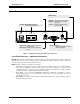
CTI Products, Inc. NCB-EL/FL User Guide QUICK-START GUIDE This Quick Start Guide provides a concise series of steps to get a pair of the NCB-Etherlon or NCB-Fiberlon modules “up and running” quickly so that initial operation may be confirmed. It is highly recommended that a pair of NCB-Etherlon or NCB-Fiberlon modules be tested in your application by first connecting them “back-to-back” with the 10BaseT or fiber crossover cable included with this shipment.
CTI Products, Inc. NCB-EL/FL User Guide 1. INTRODUCTION WHAT ARE NCB UNITS? Read this section to learn the general function and capabilities of an NCB Router The Network Combiner NCBTM Module is a device that, when used in pairs, allows multiple LONW ORKS networks to be connected in real-time, spanning distances from building-wide to worldwide.
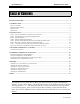
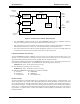
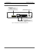
CTI Products, Inc. NCB-EL/FL User Guide “NETWORK” Connector ROUTER LONWORKS NETWORK LONWORKS TRANSCEIVER Side B “10BaseT” Connector Side A SMX TRANSCEIVER CONTROL NEURON PROCESSOR To Ethernet Channel “AUI” Connector POWER SUPPLY “DC IN” Connector Figure 2 NCB Network Combiner Block Diagram • The “NETWORK” connector attaches to the local LONW ORKS network using a compatible transceiver internal to the NCB module and is associated with Side B of the internal router.
CTI Products, Inc. NCB-EL/FL User Guide Control Neuron Processor The Control Neuron Processor provides access to IP address parameters. Ethernet channel parameters can be configured and displayed using the EtherPlug program. The Control Neuron Processor acts as another LONW ORKS node on the network. It is connected to Side A of the router module, and appears to be located on the Ethernet channel. Ethernet Port The 10BaseT and AUI connectors implement IEEE standard Ethernet at 10 Mbps.
CTI Products, Inc.
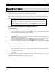
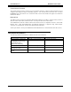
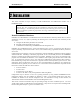
CTI Products, Inc. NCB-EL/FL User Guide REAR PANEL OPTION Switches Selects the active Ethernet connector. (See Step 6 of Installation section. 10BASE-T DC IN Connector for input power AUI DC IN OPTION ON 1 2 3 4 5 6 7 8 Ethernet Connectors Only one can be used at any one time (selected by OPTION switches) Figure 4 NCB-Etherlon and NCB-Fiberlon Rear Panel 2.
CTI Products, Inc. NCB-EL/FL User Guide 2. INSTALLATION This section describes the steps necessary to install NCB-Etherlon and NCB-Fiberlon modules into a LONW ORKS system. NOTE : DO NOT connect the NCB-Etherlon or NCB-Fiberlon modules to a live IP network until they have been reconfigured with new IP addresses and subnet mask supplied by the network manager. Network-wide problems could arise from connecting devices to a network without coordination of addressing information.
CTI Products, Inc. NCB-EL/FL User Guide STEP 1 . INSTALL ETHERPLUG CONFIGURATION SOFTWARE This step installs the .XIF file for the Control Neuron Processor and the EtherPlug configuration software. The EtherPlug configuration software will be used to configure IP address parameters of NCB modules, and is included on the CDROM shipped with the NCB units. EtherPlug is a Windows application compatible with Windows 95/98 and Windows NT.
CTI Products, Inc. NCB-EL/FL User Guide worst case delay between NCB modules. See Steps 7C and 7D. • Enter a channel “Description”, if desired. Then Click OK to continue. B) Add the standard LONWORKS router portion of the NCBs to the network drawing: • Drag the Router shape to the drawing. The “New Router Wizard” window will be displayed. • Specify the desired router “Name”, and click NEXT to continue.
CTI Products, Inc. NCB-EL/FL User Guide Figure 5 Example LonMaker Drawing STEP 3. START ETHERPLUG Note : If installing NCB-Fiberlons on dedicated fiber segments, skip to Step 6. The EtherPlug configuration software provides access to IP address parameters for NCB-Etherlons and NCBFiberlons as a standalone program launched directly from the Windows Start menu or as an LNS Plug-in from within an LNS-based application such as LonMaker for Windows.
CTI Products, Inc. NCB-EL/FL User Guide Figure 6 Main EtherPlug window (started as an LNS Plug-in) When launched as an LNS Plug-in: • EtherPlug retrieves information from the LNS database for the channel that was selected before starting EtherPlug. • The name of the channel selected before launching the Plug-in is shown in the Channel Name box. • All NCB Control Neuron Processor devices present on the custom Ethernet channel are automatically listed in the “Channel Member List”.
CTI Products, Inc. NCB-EL/FL User Guide STEP 4. EDIT IP ADDRESS PARAMETERS Note : If installing NCB-Fiberlons on dedicated fiber segments, skip to Step 6.
CTI Products, Inc. NCB-EL/FL User Guide • For all remote NCB units that need to exchange LONW ORKS packets with only the Central Site NCB, set its Targets selection to Central Site. • MAC Refresh: If the Ethernet port of an NCB is connected to an IP MAC layer switch, specify a MAC Refresh value other than Disabled for that member to cause the NCB to periodically notify that switch of the existence of this NCB.
CTI Products, Inc. NCB-EL/FL User Guide after the cable has been connected. The “Downloading” window will be displayed. downloading has completed successfully, the “Sync” field will change to a green ‘9’. When • The “Instructions” window will prompt to connect the selected COM port to the next NCB Member. Click OK the cable has been connected. Continue this process for all NCB units. • When downloading is complete to all members, the “Channnel Sync” indicator will change to a green ‘9’.
CTI Products, Inc. NCB-EL/FL User Guide C) Make electrical connections (See Appendix C for connector details): Grounding • When wall or rack mounting the NCB, a suitable safety and protective earth ground should be provided to the metal enclosure. The protective earth ground provides a path to ground for electrostatic discharge (ESD) energy. This connection is most conveniently made directly to the wall mount bracket or rack plate.
CTI Products, Inc. NCB-EL/FL User Guide STEP 7. COMMISSION THE ROUTERS AND CONTROL NEURON PROCESSORS Once the NCB unit IP Address Parameters are set (steps 4 and 5) and the NCB units are physically installed in the IP and LONW ORKS networks (step 6), the router and control neuron processor portions of each NCB unit must be commissioned with the LONW ORKS network management tool.
CTI Products, Inc. NCB-EL/FL User Guide INSTALLING ADDITIONAL NCB UNITS AFTER INITIAL INSTALLATION Should additional NCB units need to be installed after the initial installation has been completed, use one of the two following sequences: If using Multicast IP Address Mode: 1. Add the new NCB units to the network management tool per Step 2 above. 2. Start EtherPlug and edit the IP Parameters for the new NCB units per Step 3 and Step 4 above. 3.
CTI Products, Inc. NCB-EL/FL User Guide 3. NETWORK VARIABLE (NV) CONTROL All commands sent to the NCB module are carried on the LONTALK network in the form of Network Variables bound to the Control Neuron processor inside the NCB module (connected to Side A of the internal router). This section details the network variables associated with the Configuration Object. These network variables are not used in a typical application, but are documented here for specific cases requiring them.
CTI Products, Inc. NCB-EL/FL User Guide Ping Request (Input) C Language Syntax typedef struct U_PING_REQ { unsigned char ip[4]; unsigned char rpt; unsigned short t_out; 0; 4 byte IP address repeat count time-out (ms) 16 bits (2 bytes) required zero } Usage This input network variable structure requests an IP ping of the specified IP address. The Repeat Count specifies the number of pings issued and must have a value between 1 and 255.
CTI Products, Inc. NCB-EL/FL User Guide 4. ETHERPLUG ADDITIONAL FUNCTIONS Basic usage of the EtherPlug configuration software is described in SECTION 2 of the manual. This section covers additional features of EtherPlug not described in SECTION 2.
CTI Products, Inc. NCB-EL/FL User Guide APPENDIX APPENDIX A. FACTORY DEFAULT CONFIGURATION Control Neuron Processor Restoring Factory Default Communication Parameters If the Control Neuron Processor or router module communication parameters are overwritten by a network management tool, they can be restored as follows: • Press the “RESET” button on the front of the NCB unit • After the “ERR” LED goes off, press the “RESET” button a second time.
CTI Products, Inc. NCB-EL/FL User Guide Querying, Defaulting, and Unconfiguring Router Configuration using SETRTR.EXE The SETRTR.EXE DOS utility provided with each NCB can be used to query the router for its current configuration, force the router to certain default states, or force the router to unconfigured mode.
CTI Products, Inc. NCB-EL/FL User Guide APPENDIX B. MOUNTING OPTIONS Wall mount and EIA 19” rack mount kits are available as options for the NCB from CTI Products, Inc. The wall mount kit includes brackets to allow a single NCB module to be mounted to any flat surface. The rack mount kit includes an adapter allowing up to three NCB modules to be mounted in a single rack unit height. Rack Mount Option The rack mount option allows up to three NCB modules to be mounted in a one rack unit height (1.
CTI Products, Inc. NCB-EL/FL User Guide To attach a module to the rack adapter, and then mount the rack adapter into the rack, follow the steps below. WARNING Do not allow the PC board to slide out of the housing when the front panel is removed. If it does, DO NOT slide the PC board back into the housing from the front of the module. Doing so may damage the unit, causing the unit to malfunction when powered on. Doing so will void the unit’s warranty.
CTI Products, Inc. NCB-EL/FL User Guide Wall Mount Option The wall mount option allows an NCB module to be mounted to any flat surface. The NCB module has four screw holes on the bottom. Simply attach the two mounting plates to the bottom of the module using the four flat-head screws provided with the wall mount kit. This assembly is then attached to the flat surface with userprovided fasteners. Figure 8 shows a dimensioned view of the wall mount installation.
CTI Products, Inc. NCB-EL/FL User Guide APPENDIX C. CONNECTOR DETAILS DC IN Connector Connector type: 2.5 x 5.5 mm coaxial Mating Connector: Switchcraft 760 or equivalent Connector pinout: CTI Products, Inc. standard power supply is wired with center pin positive, NCB module can accept either pin positive, polarity routing is provided internal.
CTI Products, Inc. NCB-EL/FL User Guide SMX Transceiver units: SMX network connections are described in the documentation with the SMX transceiver. NETWORK Ethernet Connectors 10BaseT Connector: AUI Connector: Connector type: Standard RJ-45 female. Connector type: Standard DSubminiature 15 pin Pin 1 2 3 4 5 6 7 8 Function Ethernet TX Ethernet TX Ethernet RX N/C N/C Ethernet RX N/C N/C Pin 1 2 3 4 5 6 7 8 9 10 11 12 13 14 15 2 1 female.
CTI Products, Inc. NCB-EL/FL User Guide APPENDIX D. TROUBLESHOOTING Table D1 If the PWR LED . . . REASON CORRECTIVE ACTION Is always illuminated. Normal operation indicating that NCB unit is receiving proper DC input power. Go to next Table. Does not illuminate. NCB unit is not receiving DC input power. Check for proper voltage at “DC IN” connector (10-32VDC). Table D2 If the ERR LED . . . REASON CORRECTIVE ACTION Is always off. Normal operation indicating no error condition was detected.
CTI Products, Inc. NCB-EL/FL User Guide Table D4 If the ETH RX LED (on local NCB) . . . REASON CORRECTIVE ACTION Occasionally blinks on, then off. Normal operation indicating a message packet has been detected on the IP network. Go to next Table. Does not illuminate when “RSVC” button on remote NCB is pressed. 1. Ethernet port is not terminated correctly to the IP network. 1a. Verify that OPTION switch positions 7 and 8 are set correctly for the Ethernet connector being used.
CTI Products, Inc. NCB-EL/FL User Guide Table D5 If the ACT LED (on local NCB) . . . REASON CORRECTIVE ACTION Occasionally blinks on, then off. Normal operation indicating a message packet has passed through the router module of the NCB. Go to next Table. Does not illuminate when “RSVC” button on remote NCB is pressed. 1. LONW ORKS Service Pin message from remote NCB is not reaching the local NCB. 1a. Verify that “ACT” and “ERR” LED’s on remote NCB flash once.
CTI Products, Inc. NCB-EL/FL User Guide Table D6 Miscellaneous: REASON CORRECTIVE ACTION Cannot communicate with Control Neuron Processor of local NCB when using NODEUTIL. 1. In Bridge or Configured modes, router neurons and network interface are not in the same domain. 2. In Repeater mode, the network interface may be defective. Verify that NODEUTIL can communicate with another LONW ORKS node. 2a. Place the local router in Repeater mode and verify that communications is possible, or b.
CTI Products, Inc. NCB-EL/FL User Guide APPENDIX E. SPECIFICATIONS NCB-Etherlon and NCB-Fiberlon DC Power Input: 10 to 32 VDC, unregulated (10BaseT) 15 to 32 VDC unregulated (AUI) 5 watts maximum without SMX transceiver 10 watts maximum with SMX power line transceiver Size: 7.5” D x 5.6” W x 1.
CTI Products, Inc. NCB-EL/FL User Guide APPENDIX F. IP ADDRESSING Conventions Any node connected to an IP (Internet Protocol) network must be identified with a unique 32-bit address. These 32-bit addresses are commonly written in dotted decimal notation as four decimal numbers (referred to as octets because each decimal number represents 8 bits) separated by decimal points. Each octet can be a number from 1 to 255. For example, 131.9.1.2 is a valid IP address.
CTI Products, Inc. NCB-EL/FL User Guide IP Addressing modes Unicast/Replicated Unicast/Replicated addressing mode allows point-to-point or point-to-multipoint communications in any IP network. A table of Target IP Addresses is configured into each of the NCB-Etherlon™ Routers, the table in each containing the IP addresses of the other modules in the group. The maximum number of NCBs that can be configured into one Unicast/Replicated group is 96.
CTI Products, Inc. NCB-EL/FL User Guide When a message is destined for an IP address whose MAC address has not yet been resolved, an ARP REQUEST is sent from the local host as a broadcast message, asking for MAC identification. A remote host with the IP address in question generates an ARP RESPONSE. This ARP RESPONSE contains the requested MAC address. The local host receives the message, and places the IP Address and the matching MAC Address in its ARP Cache.
CTI Products, Inc. NCB-EL/FL User Guide INDEX A Address Resolution Protocol......................... See ARP B Bridge........................................................................ 3 Broadcast ................................................................ 35 Buffer Configuration............................................... 21 C Configured router................................................ 3, 22 Connector................................................................