
Manual

CTI Products, Inc. NCB-EL/FL User Guide
2. Installation 9
worst case delay between NCB modules. See
Steps 7C and 7D
.
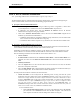
•
Enter a channel “
Description”
, if desired. Then Click
OK
to continue.
B) Add the standard
L
ON
W
ORKS
router portion of the NCBs to the network drawing:
•
Drag the
Router
shape to the drawing. The
“New Router Wizard”
window will be displayed.
•
Specify the desired router “
Name”
, and click
NEXT
to continue.
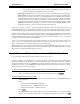
•
In the “
Channel A
”
Name
field, choose the custom Ethernet channel created in
Step A
(if this
custom channel does not appear, be sure the
Xcvr Type
field is set to
All
). In the “
Channel B
”
Name
field, choose the standard
L
ON
W
ORKS
channel that the
NETWORK
connector on the NCB
module is connected to. Click
NEXT
to continue.
•
Specify a “
Location”
and “
Description”
, if desired. “
Ping Interval
” can be set as desired. Click
NEXT
to continue.
•
Specify desired advanced router properties.
Router Type : Configured
is recommended.
•
Click
FINISH
to complete the
“New Router Wizard”
.
•
Repeat
Step B
for all NCB modules connected to the custom Ethernet channel created in
Step A
.
C) Add the Control Neuron Processor of the NCBs to the network drawing:
•
Drag the
Device
shape to the drawing. The
“New Device Wizard”
window will be displayed.
•
Specify the desired “
Device Name”
. These name given to each Control Neuron Processor should
correlate directly with the name of each associated router defined in step B above. Click
NEXT
to
continue.
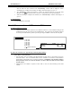
•
In the “
External Interface Definition
” section, choose “
Existing Template
”, click the down
arrow and choose the “NCBEL20” template. This template is automatically transferred to the
L
ON
W
ORKS
\import
directory during installation of the EtherPlug software. Click
NEXT
to
continue.
•
In the “
Channel: Name
:” section, choose the custom Ethernet channel connected to
Side A
of the
router that was created in
Step A
(if this custom channel does not appear, be sure the
Xcvr Type
field is set to
All
). Click
NEXT
to continue
•
Specify a “
Location”
and “
Description”
, if desired. “
Ping Interval
” should be left at
Never
.
•
Click
FINISH
to complete the
“New Device Wizard”
.
•
Repeat
Step C
for all NCB modules connected to the custom Ethernet channel created in
Step A
.
There is no need to place Functional Blocks of the Control Neuron Processors on the LonMaker drawing unless
network variables will be used to interact with this device (network variables are used only in very isolated
cases). Network variables are discussed in section “3. N
ETWORK
V
ARIABLE
C
ONTROL
”.
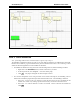
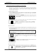
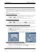
A portion of an example LonMaker network drawing is shown in Figure 5. This network may consist of a
router at each floor of a multi-floor building. The drawing depicts the Ethernet channel for Building 100 and
the routers and network channels for the first two floors. The routers named
“Router – Room …”
are the
routers inside each NCB. The devices named
“CNP – Room …”
are the Control Neuron Processors inside each
NCB.