
Manual

CTI Products, Inc. NCB-EL/FL User Guide
2. Installation 12
S
TEP
4.
E
DIT
IP A
DDRESS
P
ARAMETERS
Note : If installing NCB-Fiberlons on dedicated fiber segments, skip to Step 6.
The IP information that was gathered from the IP Network Administrator, as described at the beginning of
section 2 of this manual, must be entered into the EtherPlug program as follows:
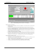
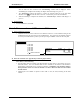
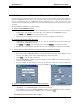
A) Specify the Channel Global IP Parameters:
•
After reviewing the information concerning
IP Addressing Modes
in Appendix F, choose either
“Unicast/Replicated” or “Multicast” from the “
IP Address Mode
” drop-down list.
•
If “Multicast” was selected above, enter the
Multicast IP Address
that the IP Network
Administrator has assigned to this group of NCBs.
•
Click on the “
Global IP Subnet Mask
” textbox, then enter the
Subnet Mask
assigned the the
NCB units by the IP Network Administrator.
•
If different subnet masks are specified for different groups of NCB units, enter the subnet mask
that is common to most of the NCB units in the group.
•
If a different subnet mask is assigned to every NCB unit, leave this field with its default value.
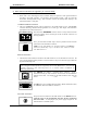
B)
Specify the “
Channel Member List
”
parameters:
If EtherPlug was launched as an LNS Plug-in, the names of all Control Neuron Processors attached to the
custom Ethernet channel will already be listed in the
Channel Member List.
If EtherPlug was launched as a standalone program, use the
Add New Member
button to add a line in the
Channel Member List
and enter the name for each NCB unit connected to the custom Ethernet channel.
Enter the following information for each NCB unit in the
Channel Member List
:
•
Host IP Address
•
IP Subnet Mask
(if different than the “
Global IP Subnet Mask
”). With
IP Subnet Mask
set to
GLOBAL, the value set in the
Global IP Subnet Mask
field is used as this member’s IP Subnet
Mask
•
Gateway IP Address
•
Leave the
Targets
field set to
All in Channel
unless
Central Site
mode is to be used, see the bullet
below for a description of this mode.
•
Leave the
MAC Refresh
field to
Disabled
unless the NCB is connected to an Ethernet MAC layer
switch or intelligent hub. See the bullet below for further information.
Several special cases should be considered, as discussed below:
•
Central Site Mode:
If
Unicast/Replicated
IP Addressing mode is being used and the system
application using these NCB units requires
L
ON
W
ORKS
messages to pass
only between devices
connected to a single NCB unit at the host computer and devices connected to NCB units at remote
locations
,
Central Site
mode can be used to reduce network traffic. To restate, if the system being
constructed
does not require
L
ON
W
ORKS
messages to flow between devices at different remote
sites, but only between a remote site and a single central site
, use
Central Site
mode. If
L
ON
W
ORKS
messages must flow between remote sites and the Central site
and also from one
remote site to another remote site,
do not
use Central Site mode.
To use Central Site mode :
•
Set
IP Central Site Member Name
to the name of the NCB unit with its NETWORK
port connected to the
L
ON
W
ORKS
network from the Host Computer. This must be the
same computer on which the network management software is being run.